AGV Drive Wheel Electromagnetic Brakes: Holding vs. Dynamic Braking, Sizing Calculations, and ISO 3691-4 Integration
Size AGV drive wheel electromagnetic brakes for ramp holding and emergency stops. Compare braking methods, check response delays, and prepare your supplier RFQ.
For an AGV drive wheel, specify three separate capabilities: holding torque on the worst ramp, dynamic stopping energy, and the complete stop-response time. A catalogue line such as “24 VDC, 10 Nm brake” does not establish all three. Use the motor and inverter for controlled service deceleration where the architecture permits, and select the mechanical brake for its documented holding and emergency-stop duties.
Scope and review date: Global / English, 28 October 2026. This guide supports AGV/AMR engineers and OEM procurement teams comparing motor-shaft spring-applied brakes. The calculations and timing examples are preliminary analytical examples, not measured product results or compliance certificates. Direct wheel-axle brakes, trailers, public-road vehicles, explosive atmospheres, and special environmental hazards require separate assessment.
For a component review, compare our AGV forklift steering drive wheels or send your application requirements, including gross mass, ramp angle, wheel radius, speed, and stopping duty.
1. How a Spring-Applied Electromagnetic Brake Works
Springs clamp a friction rotor when the coil is de-energized; coil current pulls the armature back to release it. “Power-off” describes this operating principle. It does not guarantee a safe vehicle stop under every mechanical or electrical fault.
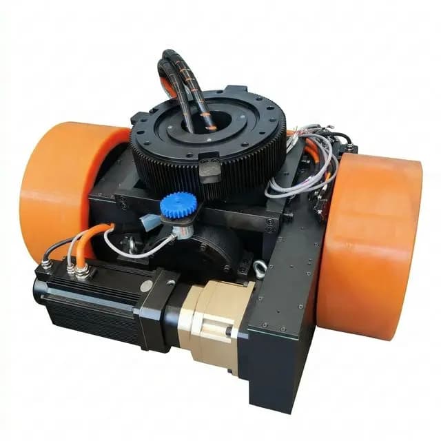
Product exterior illustration: this photograph does not expose a brake or verify its mounting position. Request a sectional drawing for the quoted drive unit before confirming brake location and service access.
A typical assembly contains a magnet body and coil, compression springs, a moving armature, a splined friction rotor, and a counter-friction surface. Air gap, lining material, permitted speed, and coil duty are model-specific.
In a motor-shaft brake, gearbox reduction increases the wheel-side resisting torque. This saves brake space but makes the gearbox, shaft connections, and mounting interfaces part of the holding path. A wheel-axle brake acts after the reduction and requires a separate torque calculation.
2. Holding vs. Dynamic Friction Braking vs. Electrical Deceleration
The table describes capabilities to verify; it does not assign universal duty ratings to brake families.
| Engineering question | Holding brake | Dynamic-rated friction brake | Motor/inverter electrical braking |
|---|---|---|---|
| Primary duty | Park and hold a stationary load | Absorb specified stopping work | Provide controlled service deceleration |
| Required torque data | Minimum holding torque over life and temperature | Dynamic torque versus speed and temperature | Available braking torque over the speed range |
| Energy limit | Emergency work only if explicitly rated | Single-stop, repeated-stop, and lifetime work | Battery acceptance, bus voltage, and resistor capacity |
| Wear mechanism | Wear from engagement while rotating and emergency events | Friction wear during dynamic stops | No brake-lining wear; motor and inverter thermal limits remain |
| Response on power loss | Springs apply after the coil and mechanics respond | Depends on actuation and design | Deceleration may be lost without an adequate energy/control path |
| Traction boundary | Excess torque can lock a lightly loaded wheel | Modulation depends on brake hardware | Slip control depends on sensing and controller capability |
| Main procurement evidence | Holding-torque tolerance and release/engagement data | Energy-speed curves and inspection limits | Braking envelope and full-battery behavior |
| Safety integration | One element in a validated holding function | One element in a validated stopping function | Ordinary regenerative braking is not automatically a safety-rated stop |
Why repeated dynamic stops can damage a holding brake
Friction work generates heat. Exceeding the selected brake's permitted energy, engagement speed, or stop frequency can cause overheating, accelerated wear, glazing, and reduced torque. There is no universal percentage loss, lining temperature, or annual emergency-stop allowance for all AGV holding brakes.
For scale, a vehicle of 1,500 kg total mass at 1.8 m/s has 2,430 J of translational kinetic energy before rotational energy is counted. This calculation does not establish how much heat reaches each brake: motor braking, tire slip, load sharing, and the drivetrain all affect the energy path. Use the selected brake's ratings and the actual stop sequence.
3. Sizing Calculations: Holding Torque and Stopping Work
3.1 Preliminary holding-torque estimate on a ramp
Ignoring beneficial rolling resistance, the gravitational wheel torque is:
F_slope = m_total * g * sin(theta)
T_wheels_total = F_slope * r_wheel
T_per_brake_screen = T_wheels_total * S / (n * i * k)m_total: vehicle mass plus maximum payload, in kg.g: 9.81 m/s²;theta: ramp angle, in degrees when using a degree-mode sine. A 4° ramp is about 7% grade, not 4% grade.r_wheel: loaded rolling radius, in m;i: motor-speed/wheel-speed reduction ratio.n: number of brakes credited with sharing the holding demand in the case being assessed.k: assumed wheel-side torque transfer factor for this preliminary model. Confirm the static and backdriven behavior with the gearbox supplier; forward running efficiency is not a measured static holding factor.S: project design margin. The example uses 1.75 as an assumption, not a universal factor mandated by ISO 3691-4 or EN 1175.
Worked example, not a tested vehicle: 2,000 kg gross mass, 4° ramp, 0.125 m wheel radius, 28:1 reduction, two equally loaded braked drives, k = 0.88, and S = 1.75.
F_slope = 2000 * 9.81 * sin(4°) = 1368.65 N
T_wheels_total = 1368.65 * 0.125 = 171.08 Nm
T_per_brake_screen = 171.08 * 1.75 / (2 * 28 * 0.88) = 6.08 Nm
Sourcing decision: use 6.08 Nm per brake as a screening demand under these assumptions. An 8–10 Nm nominal option is only a candidate: obtain its minimum guaranteed holding torque over temperature, wear, and tolerances. The margin is already included; do not multiply it twice. If a fault case credits only one brake, the same screening model gives 12.15 Nm for that brake.
Also verify tire traction: the downhill force must not exceed the available tire-floor friction force at the braked wheels. More motor-shaft torque cannot prevent a locked wheel from sliding. Unequal wheel loading and gearbox or shaft failure require separate cases.
3.2 Dynamic energy absorption per stop
For a level-floor screening calculation, include translational energy and each rotating assembly once:
W_total = 0.5 * m_total * v_0² + sum(0.5 * J_j * omega_j²)
omega_motor = v_0 * i / r_wheel
Here J_j is each assembly's inertia in kg·m² and omega_j is its angular speed in rad/s. Do not add separate rotor energy if the mass model already includes it through an equivalent-mass correction. Downhill stopping also adds gravitational work over the stopping path.
For the 2,000 kg vehicle at 1.8 m/s, assuming rotational energy equals 10% of translational energy:
W_translational = 0.5 * 2000 * 1.8² = 3240 J
W_rotational_assumed = 324 J
W_total = 3564 J
W_per_brake_assumed_equal_share = 3564 / 2 = 1782 J
The 10% allowance and equal split are illustrative assumptions. Compare the resulting 1,782 J per brake with the manufacturer's permitted work at the actual engagement speed, plus stop frequency, cooling conditions, cumulative lifetime work, and post-stop torque. A nominal 10 Nm rating does not imply any particular joule capacity. On a downhill stop, include potential energy; under faults, verify the actual energy split.
3.3 Stopping distance and response time
For a mechanical-stop case approximated by constant speed during reaction followed by constant deceleration:
t_response = t_sensor + t_logic_and_communications + t_output + t_brake_engagement
s_total = v_0 * t_response + v_0² / (2 * a)
t_brake_engagement must cover the supplier-defined interval until useful braking torque develops, not just coil current decay. Avoid double-counting intervals included in a supplier's measured response time.
At 2.0 m/s, with an assumed 0.10 s response and assumed 1.0 m/s² constant deceleration, the result is 0.20 + 2.00 = 2.20 m. This is a calculation example, not a scanner protective-field setting. Slope, speed tolerance, wheel load, traction, brake wear, safety-device requirements, and measurement uncertainty remain to be assessed.
For SS1, electrical deceleration may begin before mechanical brake engagement. Model that sequence separately rather than adding every mechanical delay ahead of the electrical ramp.
4. Coil Suppression: Response Time vs. Switching Protection
A freewheel diode across a DC coil protects switching hardware but can prolong current decay. A higher approved clamp voltage can accelerate demagnetization, at the cost of higher voltage stress. Selection must cover the entire circuit, including coil insulation, output-stage ratings, EMC, and fault detection.
For a simplified coil discharge loop:
L * di/dt + R * i + V_suppression(i) = 0
Additional coasting distance = vehicle speed * additional response time
The resistance term matters; decay is not determined by diode forward voltage alone. Coil temperature, inductance, armature position, dropout threshold, wiring, and the driver all affect the measured engagement response.
| Suppression approach | Response consideration | Main limit to verify |
|---|---|---|
| Freewheel diode | Can extend current decay | Complete stop-time budget with the actual coil |
| Diode plus resistor | Additional discharge resistance can shorten decay | Pulse energy, temperature rise, and switch voltage |
| MOV | Higher clamp can accelerate decay | Clamp tolerance, repeated surge energy, and aging |
| TVS arrangement | Defined avalanche behavior can limit voltage | Polarity/topology, pulse energy, and voltage headroom |
| Active driver | Can control demagnetization | Manufacturer compatibility and fault response |
| No suppression | Uncontrolled voltage and arcing | Not an acceptable substitute for a rated protection circuit |
RFQ requirement: ask for the precise definition and measured maximum of coil release time and brake engagement time with the proposed driver and suppression circuit. Do not assume that a diode is always unacceptable or that a MOV always achieves 40 ms.
For an illustrative additional delay of 0.20 s at 2.0 m/s, the additional coasting distance is 0.40 m. Obtain the actual delay from the selected hardware before applying this arithmetic to a stopping budget.
5. Braking Control Sequences and Safety Interlocks
This diagram shows two design paths. Stop categories describe the stopping behavior; STO and SBC describe particular safety functions. STO alone does not provide mechanical braking or prevent gravity-driven movement.
6. ISO 3691-4 Integration and Functional Safety Boundaries
ISO 3691-4:2023 addresses safety requirements and verification for driverless industrial trucks and their systems. ISO 13849-1:2023 provides a methodology for safety-related control-system design; its catalogue abstract explicitly states that it does not prescribe the required safety functions or performance levels for particular applications.
Use the applicable machinery standard and vehicle risk assessment to specify each safety function, required performance level, stopping behavior, and validation evidence. Do not infer universal “PL d, Category 3” compliance from a two-channel brake output. The published 2023 edition of ISO 3691-4 remains the reference cited here; the ISO catalogue also lists a revision in development. Confirm the edition and local adoption required by the project before design approval.
These public catalogue records establish scope and edition status, not clause-level proof of a brake design. The examples in this article do not establish conformity in any jurisdiction.
6.1 SS1, STO, and safe brake control
In IEC 61800-5-2 terminology, SS1 provides controlled deceleration followed by STO; monitoring and timing depend on the selected implementation. STO prevents torque generation by the drive and does not itself apply a brake or remove all electrical hazards. SBC provides safe control of an external brake, not a guarantee of mechanical brake torque.
Specify a coordinated handover that supports the load while the mechanical brake develops torque, with appropriate feedback or timing and fault response. Verify drive documentation and the applicable standard text before claiming an SS1/SBC safety function. Regeneration also needs an energy destination: check behavior with a fully charged battery and the braking-resistor/DC-bus limits.
If redundant switching is used, assess short circuits, cross faults, diagnostic coverage, common-cause failures, and switching-device reliability. Whether high-side, low-side, or both switching elements are used is an implementation decision requiring validation. Two outputs alone are insufficient evidence.
6.2 Brake release feedback and proof testing
A microswitch or inductive sensor can confirm armature movement and help prevent driving against an unreleased brake. Use the supplier's specified signal polarity, release-time tolerance, and diagnostic behavior. A position signal cannot prove the friction lining's holding torque or the integrity of the full drivetrain path.
Set the release timeout from the worst-case rated response at minimum supply voltage, maximum permitted temperature, and worn air gap. There is no universal 80 ms threshold. Define separate holding-torque proof tests and service limits where required by the safety concept.
6.3 Overexcitation and PWM economizing
Some brake drivers use a short pull-in phase followed by lower holding current to reduce coil heating. Use only the coil/driver combination approved by the manufacturer. Applying 48 V to a nominal 24 V coil without an approved voltage-time envelope can damage it.
Request permitted pull-in voltage and duration, minimum holding current, PWM characteristics, insulation temperature, and engagement behavior at switch-off. Energy savings depend on the actual current waveform and resistance; a generic percentage is not a product guarantee.
7. Disabled-Vehicle Recovery and Manual Release
Dragging a vehicle with clamped wheels can damage tires and drivetrain components. Plan a recovery method before the chassis layout is frozen.
An accessible mechanical release or an approved auxiliary electrical release can permit controlled recovery. The design must prevent unintended rollback, preserve a defined safety state, and allow confirmation that braking has been restored. Spring-return levers are one option; other release mechanisms require their own safeguards and restoration procedure.
Before releasing a brake, secure the vehicle and load with appropriate restraints, assess slope and towing direction, isolate unintended drive motion, and follow the manufacturer's speed and distance limits. An auxiliary supply must be part of an approved recovery circuit; do not improvise a direct battery bypass of the brake-control system.
8. Drive Wheel Brake Options: What to Put in the RFQ
Treat these entries as questions for a supplier, not as specifications automatically supplied by an environmental label.
| Sourcing parameter | Required application input | Evidence to request |
|---|---|---|
| Holding torque | Gross mass, ramp angle, radius, load sharing, fault cases | Minimum torque over tolerance, wear, and temperature |
| Dynamic work | Engagement speed, energy per stop, stops per hour | Permitted energy-speed curve and lifetime friction work |
| Coil voltage | Battery minimum/maximum and wiring voltage drop | Approved coil/driver voltage and duty envelope |
| Response time | Complete vehicle stopping-time budget | Worst-case engagement/release times with the actual suppressor |
| Release feedback | Safety concept and startup sequence | Signal definition, diagnostic limits, and sensor rating |
| Recovery | Access, slope, towing method, restoration process | Approved release mechanism and instructions |
| Environment | Temperature, condensation, oil, dust, cleaning agents | Assembly ratings and relevant qualification evidence |
| Service access | Inspection interval and replacement strategy | Air-gap limits, wear criteria, and maintenance procedure |
For high-load platforms, compare the integration constraints with our heavy-duty AGV drive wheels and request confirmation of the brake option on the quoted model.
9. OEM Engineering and Procurement Checklist
Mechanical and thermal integration
- Calculate worst-ramp holding demand using gross mass, loaded wheel radius, and documented load sharing; include the project margin once.
- Confirm static/backdriven gearbox behavior, shaft and mounting strength, tire traction, and relevant single-fault cases.
- Obtain minimum guaranteed holding torque rather than relying only on nominal torque.
- Check dynamic engagement speed, single-stop work, repeated-stop heating, lifetime friction work, and downhill energy.
Electrical and control integration
- Match coil and driver ratings to the battery voltage range, wiring losses, temperature, and permitted duty.
- Obtain measured maximum response times with the proposed suppression circuit and avoid double-counting timing intervals.
- Confirm release-sensor behavior, startup interlocks, brake handover, and fault response.
- Check the energy path during regeneration, including a full battery and unavailable electrical deceleration.
Safety, maintenance, and recovery
- Document applicable standard editions, safety functions, required performance levels, and verification responsibilities.
- Validate stopping distance and stability over specified loads, speeds, gradients, floor conditions, wear states, and faults.
- Define air-gap inspection, torque proof testing where required, lining replacement, and post-emergency-stop inspection.
- Approve the recovery procedure, restraints, release access, towing limits, and brake-restoration check.
10. Frequently Asked Questions
Can a spring-applied holding brake handle repeated emergency stops?
Only if its manufacturer explicitly rates it for the required speed, energy per stop, stop frequency, and lifetime friction work. A static torque rating alone does not establish dynamic stopping capability. Repeated stops can overheat or wear a holding brake; request the specific brake's emergency-stop limits and inspection criteria.
Why can a flyback diode increase AGV stopping distance?
A freewheel diode limits coil overvoltage but can prolong current decay and delay spring application. A higher-voltage suppression circuit can shorten that delay if approved for the coil and switching hardware. The added coasting distance is speed multiplied by additional delay: an illustrative 0.20 s delay at 2.0 m/s adds 0.40 m. Actual response times require measurement.
How does SS1 coordinate with the mechanical brake?
SS1 provides controlled deceleration followed by STO; its timing and monitoring depend on the implementation. In a coordinated design, the drive maintains load support while the mechanical brake builds holding torque, before torque is removed. SBC controls the brake safely but does not prove available mechanical holding torque. STO alone does not stop or hold a vehicle.
How do you estimate motor-shaft holding torque on a ramp?
For preliminary screening, use T_per_brake = m * g * sin(theta) * r * S / (n * i * k), where n is the number of brakes credited with sharing the load, i is reduction ratio, and k is an explicitly assumed transmission transfer factor. With 2000 kg, 4 degrees, 0.125 m radius, two brakes, 28:1 reduction, k = 0.88, and S = 1.75, the estimate is 6.08 Nm per brake. Validate static load transfer, traction, and fault cases separately.
Does a brake release sensor prove that the brake can hold the vehicle?
No. A microswitch or proximity sensor can indicate armature position and help prevent driving against a closed brake. It does not measure available friction torque or establish a safety performance level by itself. Use the manufacturer's feedback logic and a separately defined brake proof-test and maintenance procedure.
How should a disabled AGV with spring-applied brakes be recovered?
Use the vehicle manufacturer's recovery procedure. Secure the vehicle and load before releasing a brake, especially on a slope. An approved mechanical release or auxiliary electrical release may be appropriate, with controlled towing, speed limits, and confirmed brake restoration. An improvised battery connection can bypass safety controls and must not be used.
11. Sources and Reference Boundaries
- ISO 3691-4:2023 — Driverless industrial trucks and their systems. Official scope and edition-status record, checked 28 October 2026. Use the full applicable text for vehicle requirements and verification.
- ISO 13849-1:2023 — Safety-related parts of control systems. Official methodology and scope record, checked 28 October 2026. This record does not establish a particular vehicle's required performance level.
The worked calculations are reproducible analytical examples using explicitly stated assumptions. They are not supplier test data, customer case studies, or evidence that a particular brake meets a safety standard. Request model-specific torque, energy, response-time, and safety documentation before approval.
Prepare an Application-Specific Brake Review
Send gross vehicle mass, loaded wheel radius, ramp angle or percent grade, maximum speed, gearbox ratio, number of braked drives, stopping frequency, and the intended safety concept. Include the current coil-driver/suppression arrangement and any measured stop-time data.
Compare the AGV forklift steering drive wheel range and heavy-duty drive wheel options, then contact the application team to confirm the proposed brake configuration and the evidence still needed for vehicle validation.