AGV Drive Wheel Suspension Systems: Rigid vs. Spring vs. Hydraulic Designs
Compare AGV drive wheel suspension options for rigid, spring, and hydraulic designs, then request OEM guidance for floor, traction, odometry, and TCO risks.
When specifying an AGV drive wheel for automated guided vehicles (AGVs) or autonomous mobile robots (AMRs), procurement teams and engineers often obsess over motor torque, battery chemistry, and payload capacity. However, one of the most critical factors determining the long-term reliability and navigation accuracy of an AGV is how the drive wheel interacts with the floor.
The floor is never as flat as the CAD model suggests. Real-world industrial environments are fraught with expansion joints, concrete spalling, ramps, and debris. If the drive wheel cannot dynamically adapt to these surface irregularities, the entire vehicle suffers.
This deep-dive analysis compares the three primary architectures for AGV drive wheel compliance: Rigid, Spring-Loaded (Passive), and Hydraulic (Damped) suspension systems. We will explore the physics of traction loss, the impact on SLAM (Simultaneous Localization and Mapping) odometry, and provide a definitive sourcing framework for OEM buyers and engineers.
If you are already comparing suppliers, use this article as an RFQ screen for floor tolerance, wheel load, suspension stroke, damping requirement, and cable-flex rating. Send those operating conditions to our engineering team if you need a quick suspension recommendation before freezing a prototype chassis.
1. The Physics of Traction Loss and Odometry Drift
Before evaluating suspension types, it is essential to understand the catastrophic effects of kinematic non-compliance on an AMR.
Most AGVs rely on a combination of laser scanners (LiDAR) and wheel odometry (encoder data from the drive wheels) to determine their position. The navigation algorithm assumes that for every degree the motor turns, the vehicle moves a precise linear distance. This assumption relies on one absolute requirement: The drive wheel must maintain continuous, slip-free contact with the ground.
1.1 The "Wheel Lift" Phenomenon
When an AGV with a rigidly mounted drive wheel encounters a dip in the floor—even a deviation of 2 to 3 millimeters—the wheel may lose contact with the ground. Because the motor is still receiving power, the unloaded wheel spins freely (wheel slip). The encoders report rapid movement to the vehicle's computer, but the physical vehicle has not moved. This discrepancy corrupts the odometry data, causing the SLAM algorithm to drift, miscalculate its position, or trigger a safety stop.
For the broader sensor stack behind this failure mode, see the AGV navigation method selector, which explains how wheel odometry interacts with LiDAR, markers, and SLAM correction layers.
1.2 Tire Wear and Mechanical Shock
Conversely, when a rigid wheel hits a bump, the entire kinetic energy of the heavy vehicle is transmitted directly into the polyurethane tire and the gearbox bearings. This creates massive localized stress. Over time, these impact forces cause the polyurethane tread to delaminate from the cast iron or aluminum core—a leading cause of premature drive wheel failure in 24/7 fulfillment centers.
1.3 Floor Flatness Standards and Real Warehouse Limits
Many automated warehouses attempt to solve this by specifying ultra-flat floors, often using FF/FL flatness numbers under ASTM E1155/E1155M or local construction tolerances such as DIN 18202 where applicable. However, maintaining this flatness across tens of thousands of square feet is prohibitively expensive and nearly impossible over years of heavy forklift traffic and foundation settling. A mechanically compliant drive wheel is a far more cost-effective and robust solution than attempting to pave a perfectly flawless environment.
Scope note: this guide applies to indoor industrial AGVs and AMRs operating on concrete floors with joints, ramps, wear patches, and routine debris. It does not replace a route survey, braking validation, or a safety review under driverless industrial truck standards such as ISO 3691-4.
Kinematic Compliance: Rigid vs Spring
2. Core Comparison: Rigid vs. Spring vs. Hydraulic Systems
When sourcing drive modules, OEMs must align the mechanical architecture with the intended environment. Below is a detailed technical and commercial comparison of the three main approaches.
| Feature / Metric | Rigid System | Spring-Loaded (Passive) | Hydraulic / Active Damped |
|---|---|---|---|
| Mechanical Complexity | Very Low (Direct bolt-on) | Medium (Requires guides, pivots) | High (Cylinders, fluid, valves) |
| Cost Profile | Lowest capital cost | Moderate ($200-$500 premium) | High ($800+ premium per unit) |
| Floor Irregularity Tolerance | Poor (Requires near-perfect floors) | Good (Handles joints, ramps, dips) | Excellent (Smooths severe bumps) |
| Vibration Isolation for Payload | Non-existent (100% transmitted) | Moderate (Absorbs peak shocks) | Superior (Dissipates kinetic energy) |
| Traction & Odometry Stability | High risk of wheel slip / lift | Excellent ground contact | Excellent, prevents oscillation |
| Maintenance Burden | Low (Only bearings/tires) | Low to Moderate (Spring fatigue) | High (Seal leaks, fluid checks) |
| Best Application | Cleanrooms, Light-duty, Flat floors | Warehouses, Factories, General AMR | Outdoor, High-speed, Fragile goods |
Use this table as a first filter, then run the traction case against the AGV drive wheel preload tool or the warehouse AGV drive wheel traction checker before you lock the chassis envelope. Ask for a drive wheel suspension review if you need spring preload, stroke, or damping assumptions checked.
3. Deep Dive: Rigid Drive Wheel Systems
A rigid drive wheel is bolted directly to the AGV chassis without any vertical travel mechanism. The distance between the chassis and the axle is fixed.
3.1 Engineering Characteristics
In a rigid setup, compliance must come entirely from the polyurethane tire itself. While a soft durometer polyurethane (e.g., 85A Shore) can compress slightly to absorb microscopic vibrations, it cannot accommodate a 5mm drop in the floor.
3.2 Ideal Use Cases
Rigid systems are not obsolete; they are highly specialized. They are ideal for:
- Cleanroom Environments: Semiconductor fabs or pharmaceutical plants where floors are flawlessly poured and polished, and where shedding particles from spring mechanisms is unacceptable.
- Micro-AMRs: Lightweight robots (under 50kg) moving slowly across commercial carpets or smooth tiles.
- Cost-Constrained Applications: Entry-level logistics tuggers operating in carefully controlled zones where upfront capex is tightly restricted.
3.3 The Procurement Reality
While rigid wheels appear cheaper on the initial Bill of Materials (BOM), the hidden costs can be severe. If deployed on a standard warehouse floor, the AGV manufacturer will incur massive support costs diagnosing "software navigation errors" that are actually caused by mechanical wheel slip. Furthermore, rigid wheels suffer from significantly accelerated tire degradation.
4. Deep Dive: Spring-Loaded (Passive) Suspension
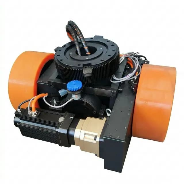
This is the industry standard for modern, heavy-duty AGVs and AMRs. The drive wheel is mounted on a pivoting swing-arm or vertical linear guide, backed by a compression spring or wave spring that pushes the wheel downward against the floor.
4.1 How It Solves the Traction Problem
The primary goal of a spring-loaded system is Normal Force maintenance. By pre-loading the spring, the engineering team guarantees that the drive wheel exerts a continuous, calculated downward force against the floor, regardless of minor dips or peaks.
If the AGV crosses an expansion joint, the spring instantly pushes the wheel down into the joint, maintaining traction and odometry integrity. If the AGV hits a bump, the spring compresses, absorbing the shock and preventing the chassis from jarring.
4.2 Types of Springs Used
- Coil Springs: The most common. They provide excellent linear travel and are easily adjustable for pre-load.
- Wave Springs: Used when vertical space (Z-height) is extremely limited inside the AGV chassis. They offer high force in a compact profile.
- Polyurethane Bushings/Dampers: Sometimes used instead of metal springs for short-travel, high-load compliance, acting as both a spring and a mild damper.
4.3 Cost-Benefit Analysis for OEMs
Adding a spring-loaded suspension module increases the component cost and requires a more sophisticated chassis cutout. However, the Return on Investment (ROI) is undeniable. It drastically reduces field failures, extends the life of the polyurethane tread, protects sensitive onboard electronics (like expensive LiDAR arrays) from vibration, and allows the AGV to operate reliably in legacy factories with imperfect floors.
5. Deep Dive: Hydraulic and Active Damping Systems
While springs are excellent at maintaining contact, they have one inherent flaw in physics: they store energy and release it. When a heavy AGV hits a bump at high speed, a pure spring system will bounce, creating an oscillation.
5.1 The Role of Damping
Hydraulic suspension systems (or spring-over-shock designs) introduce damping. A damper (shock absorber) forces oil through tiny valves, converting the kinetic energy of the bump into heat. This prevents the robot from bouncing, settling the chassis immediately after an impact.
5.2 When is Hydraulics Necessary?
Hydraulic or heavily damped systems are generally reserved for:
- High-Speed AMRs: Vehicles traveling over 2.0 meters per second, where hitting a floor transition could cause a dangerous loss of stability.
- Outdoor / Rugged AGVs: Vehicles moving between buildings across asphalt, gravel, or degraded concrete.
- Fragile Payloads: Transporting silicon wafers, delicate glass, or unsecured liquids where oscillation would ruin the payload.
5.3 Sourcing Complexities
From a procurement perspective, hydraulic systems introduce significant complexity. They are heavy, expensive, and require maintenance schedules to check for fluid leaks and seal degradation. Unless the speed or payload strictly dictates it, most indoor industrial AGVs avoid hydraulics in favor of robust passive spring designs.
6. Component Integration: Impact on Drive Wheel Design
Integrating suspension is not as simple as bolting a shock absorber to a motor. The entire kinematic design of the drive wheel module changes.
6.1 Cable Routing and Dynamic Stress
In a rigid system, power and encoder cables are static. In a suspended system, the motor and encoder move up and down continuously. Procurement must specify high-flex, robotic-grade cables for the drive wheel. Standard cables will suffer from copper fatigue and snap after a few months of suspension travel, leading to catastrophic electrical faults.
6.2 Vertical Space (Z-Height)
Suspension requires travel distance (stroke). A typical warehouse AMR might need 15mm to 30mm of vertical suspension travel. This means the internal chassis cavity housing the drive wheel must be taller, which can conflict with low-profile AMR designs intended to slide underneath carts.
7. Engineering and Sourcing Checklist
If you are an OEM buyer, engineer, or importer sourcing drive wheels for mobile robotics, do not simply accept a catalog specification. Use this checklist during your RFQ phase to validate the suspension architecture:
- Define the Floor Standard: Ask the end-user facility for their floor flatness rating (e.g., DIN 18202, F-Number system).
- Determine the Travel Requirement: Calculate the maximum floor variance (peak to trough) the AGV will encounter. The suspension stroke must exceed this number.
- Specify Pre-Load Adjustability: Ensure the spring mechanism allows engineers to adjust the pre-load tension to account for changes in AGV payload weight.
- Verify High-Flex Cabling: Explicitly demand that all motor power, brake, and encoder cables attached to the moving suspension assembly are rated for continuous dynamic flexing (minimum 5 million cycles).
- Check Z-Height Constraints: Confirm the compressed and uncompressed heights of the drive module fit within your AMR's chassis clearance limits.
- Evaluate Dampening Needs: If the AGV operates above 1.5 m/s or carries sensitive goods, require a damping mechanism (polyurethane buffer or hydraulic shock) in the quote.
If the suspension decision changes the motor envelope, compare the result with the AGV drive wheel torque and motor sizing guide. For supplier documentation, combine this section with the AGV drive wheel RFQ checklist and request matching drawings from engineering resources.
8. Frequently Asked Questions (FAQ)
Q: Can we upgrade our existing AGV fleet from rigid to spring-loaded suspension? A: In most cases, yes, but it requires chassis modifications. The internal Z-height must be sufficient to accommodate the spring stroke (typically 15-30mm), and the motor cabling must be upgraded to high-flex robotic cables. We recommend consulting the OEM before attempting a field retrofit to ensure the SLAM odometry parameters can be adjusted for the new suspension compliance.
Q: How do we determine the correct spring pre-load for our payload? A: Spring pre-load must be calculated based on the maximum Gross Vehicle Weight (GVW). The suspension should be compressed by approximately 30-50% of its total travel under static maximum load. This ensures the wheel can still push down into floor dips (rebound travel) while having room to absorb bumps (compression travel).
Q: Does suspension type affect our choice of polyurethane tire compound? A: Yes. Rigid systems often rely on softer polyurethane (e.g., 85A Shore) to provide minimal compliance, which wears out faster and suffers from chunking. A spring-loaded or hydraulic system absorbs the shock mechanically, allowing you to specify a harder, more durable polyurethane compound (e.g., 93A or 95A), significantly increasing tire lifespan and reducing maintenance intervals.
Q: Are hydraulic suspensions prone to leaking in cleanroom environments? A: Yes, which is why hydraulic systems are strictly avoided in semiconductor or pharmaceutical cleanrooms. Even microscopic fluid weepage can violate cleanroom standards. For high-grade cleanrooms, rigid wheels or fully enclosed, particle-free spring mechanisms are required.
9. Conclusion and Next Steps
Choosing the correct suspension system for an AGV drive wheel is a balancing act between mechanical complexity, cost, and operational reliability.
For highly controlled, cleanroom environments, rigid wheels offer simplicity. For heavy, high-speed, or outdoor applications, hydraulic damping is non-negotiable. However, for the vast majority of industrial warehouses and fulfillment centers, a well-engineered, spring-loaded (passive) drive wheel provides the optimal balance of traction, odometry protection, and Total Cost of Ownership.
Ignoring floor compliance during the sourcing phase will inevitably lead to SLAM navigation drift, premature tire destruction, and costly field retrofits.
If your engineering team is currently designing a new AMR chassis or upgrading a legacy AGV fleet to handle tougher industrial environments, you need drive modules designed for kinematic compliance.
Contact our engineering team to discuss your payload, speed, and floor conditions. We can help you select or customize a drive wheel module with the exact spring rates, suspension travel, and robust polyurethane compounds required to keep your robots moving reliably.
10. Sources and References
- Borenstein and Feng: Measurement and Correction of Systematic Odometry Errors in Mobile Robots - Classic mobile robot odometry reference for error mechanisms that become worse when wheel-ground assumptions break. View Source
- ASTM International: ASTM E1155/E1155M-20 - Standard method for determining FF floor flatness and FL floor levelness numbers in industrial floor evaluation. View Source
- ISO: ISO 3691-4:2023 - Safety requirements and verification framework for driverless industrial trucks and their systems. View Source