Planetary vs. Cycloidal Gearboxes for AGV and AMR Drive Wheels: Shock Load Withstand, Radial Overhung Load, Backlash Drift, and Sizing Trade-Offs
Compare planetary vs cycloidal AGV drive wheel gearboxes for shock torque, radial loads and backlash. Use the sizing example and RFQ checklist to shortlist.
For planetary vs cycloidal AGV drive wheel gearboxes, shortlist by wheel torque, radial force at the actual offset, allowable shock events and backlash acceptance conditions. A purpose-built planetary hub can be suitable for high wheel loads; a precision cycloidal reducer can be worth evaluating when low lost motion and overload capacity are priorities. Topology alone cannot approve either design.
This comparison is for AGV/AMR engineering teams and OEM buyers worldwide who have already chosen a geared drive. For the preceding architecture decision, see Direct Drive vs. Geared AGV Drive Wheels.
Scope and evidence — reviewed 2026-11-03: The equations and worked example below are reproducible screening calculations with stated assumptions, not measured hardware results or supplier approvals. Manufacturer pages support only the named product features; they do not establish universal shock multipliers, end-of-life backlash or docking precision. Local safety requirements and the exact supplier configuration still need review.
Preparing a shortlist? Send the wheel-load envelope and duty cycle for a technical RFQ, using the checklist below.
1. Why Wheel Loads Need More Than a Gearbox Torque Rating
A reducer coupled to an externally supported shaft sees a different load path from a gearbox that directly supports a wheel. Stationary machinery can also have severe loads; the key distinction is which bearings carry the forces. In a wheel-mounted drive, account for vehicle weight distribution, load transfer, tire compliance, turning scrub and floor impacts.
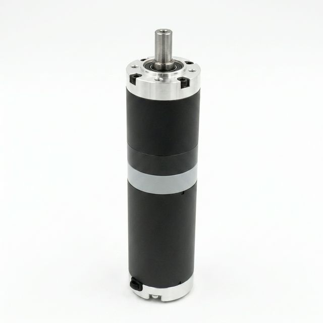
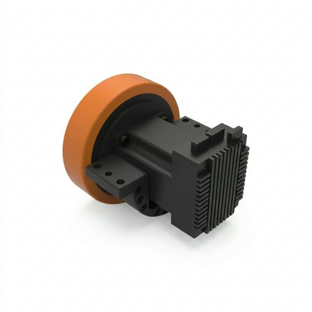
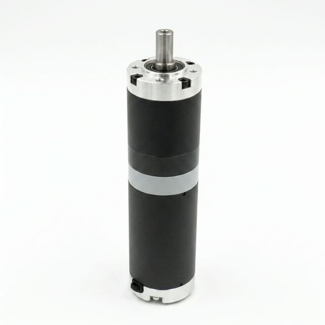
Figure 1: Geared motor reference image. No wheel or tire is shown; the image does not establish internal gear topology or wheel-load capacity.
A. Overhung Radial Force and Tilting Moment
If a wheel is cantilevered from the gearbox, its radial load acts at an offset from the bearing support datum:
M_b = F_r * L_offsetFor an assumed wheel load of 6,000 N and offset of 0.035 m, M_b = 210 Nm. Define the datum on a drawing: an offset from the mounting face is not automatically the offset from the outer bearing center. Internal bearing span and preload affect reactions and deflection.
B. Dynamic Shock Loads
A floor strike can load gear teeth, shafts, bearings and mounts. Step height, travel speed, tire stiffness, suspension, mass distribution and drivetrain compliance all influence the transient. There is no universal conversion from a 4 mm step to a torque multiplier. Record or model the transient and ask the supplier which torque limit applies to its duration and recurrence.
C. Reversals and Backlash
With motor-side feedback, reversal can produce encoder motion before the wheel responds. Output-side feedback can observe motion after the gearbox, but tire deformation and slip remain. Use a backlash and compliance budget appropriate to the actual navigation and docking system.
2. Planetary vs. Cycloidal Mechanics and Shock Capacity
The schematic illustrates different load paths. It is not a contact simulation, dimensioned design or overload rating.
A. Planetary Gearboxes: Tooth Bending and Contact Stress
A sun gear transmits torque through several planet gears and an internal ring gear. Tooth contact ratio and sharing between planets depend on tooth geometry, helix angle, tolerances, stiffness and alignment. Counting schematic contacts cannot establish shock capacity.
ISO 6336-3 provides a framework for spur/helical tooth bending assessment. A complete rating also needs the applicable contact-fatigue checks, material data, geometry and load factors. This guide does not reproduce a standards-compliant calculation or assign an application factor from floor geometry alone.
B. Cycloidal Reducers: Multiple Contacts, Model-Specific Limits
An eccentric mechanism drives lobed discs against a pin ring; some RV designs also use an initial involute stage. Several contacts can share load, but actual sharing depends on clearances and deformation. Contact fatigue, pins, eccentric bearings and output components can still limit the assembly.
For an example of published specifications, Nabtesco's product overview lists backlash and lost motion below 1 arcmin for RV-E models, while some right-angle models have different limits. This is a product specification, not evidence of unchanged backlash throughout service life or a universal 500% shock rating.
3. Cantilevered Overhung Loads and Output Bearing Architecture
A wheel-supporting gearbox needs a verified force-and-moment envelope as well as torque capacity. Check the complete hub, fasteners and chassis mounting interface.
Bearing Life Screening: What ISO 281 Does and Does Not Establish
First resolve wheel forces and moments into loads on each bearing using its arrangement and span. A simplified equivalent-load and basic-life calculation for a bearing is:
P = X * F_r_bearing + Y * F_a_bearing
L_10h = (10^6 / (60 * n)) * (C / P)^pCis the bearing's basic dynamic load rating;Pis its equivalent dynamic load, both in N.XandYcome from the bearing manufacturer's method for that bearing and loading condition; they are not universal constants.nis bearing relative speed in RPM for a constant-duty segment;p = 3for ball bearings and10/3for roller bearings.L_10his basic rating life at 90% reliability under the method's assumptions. It is not the service life of the entire gearbox. Variable-duty loads require a suitable equivalent-load calculation; static indentation, lubrication, contamination, preload and shock need separate checks.
For a hypothetical two-support shaft with wheel load F_r = 4,000 N, overhang L = 40 mm beyond the outer bearing, and bearing span S = 30 mm:
Outer bearing reaction magnitude = F_r * (1 + L/S) = 9,333 N
Inner bearing reaction magnitude = F_r * L/S = 5,333 N (opposite direction)
This is a rigid, simply supported shaft example; it is not a model for every preloaded hub or crossed-roller bearing. It illustrates why quoting wheel force without its offset can hide the bearing demand. No failure date can be inferred without bearing data and duty history.
Purpose-Built Hubs and Integrated Main Bearings
Neugart's NGV documentation describes direct chassis mounting, an output bearing arrangement using preloaded angular contact roller bearings, and installation largely inside the wheel. This provides a counterexample to the idea that planetary gears are restricted to low wheel loads. Use the configured load limits at the actual datum, not a family-wide radial-force estimate.
Some cycloidal assemblies include a main bearing; others need additional support. Verify combined radial/axial/moment capacity and life for the exact product. Neither the gear topology nor the bearing name establishes an allowable wheel load.
4. Backlash, Odometry Drift, and Docking
A. Convert Output Backlash to Tangential Lost Motion
For an assumed output-side backlash angle, the corresponding wheel-rim displacement is:
delta_s = r_wheel * (theta_arcmin / 60) * (pi / 180)The values below are calculated sensitivities, not typical specifications assigned to gearbox families. They assume a rigid wheel and full traversal of the stated angular gap.
| Wheel diameter | Assumed 12 arcmin | Assumed 3 arcmin | Assumed 1 arcmin |
|---|---|---|---|
| 150 mm | 0.262 mm | 0.065 mm | 0.022 mm |
| 200 mm | 0.349 mm | 0.087 mm | 0.029 mm |
| 250 mm | 0.436 mm | 0.109 mm | 0.036 mm |
| 300 mm | 0.524 mm | 0.131 mm | 0.044 mm |
| 350 mm | 0.611 mm | 0.153 mm | 0.051 mm |
| 400 mm | 0.698 mm | 0.175 mm | 0.058 mm |
B. Differential Drive Heading Sensitivity
For track width B, ideal differential-drive kinematics gives:
delta_psi = (delta_s_right - delta_s_left) / BIf opposing wheel displacement errors are assumed to be +0.349 mm and -0.349 mm on a 600 mm track, the heading discrepancy magnitude is 0.698 / 600 = 0.00116 rad, or about 0.067 degrees. Sign depends on the yaw convention.
This single-event bound cannot predict accumulated drift over 100 reversals. Error signs, loading, tire slip, controller compensation and external pose updates matter. Validate docking performance on the complete vehicle rather than equating a gearbox backlash number with localization accuracy.
C. Specify Backlash Drift as an Acceptance Test
Request initial and post-endurance backlash or lost-motion results at the same torque, temperature, direction and output position. Define the duty cycle and permitted increase. Separate gear clearance from torsional compliance and bearing deflection. No universal 10,000-hour drift curve or lifetime zero-backlash guarantee follows from the topology.
5. Gearbox Comparison: What Buyers Must Verify
This 12-row matrix is a shortlist framework. It intentionally uses configuration-dependent checks instead of unsupported family-wide price, efficiency or life ranges.
| Engineering parameter | General planetary gearhead | Purpose-built AGV planetary hub | Precision cycloidal / RV assembly | Right-angle hypoid / bevel assembly |
|---|---|---|---|---|
| Load path | Sun, planets and ring; wheel support may be external | Planetary stage integrated with a wheel-support concept | Eccentric discs and pins; RV may include a gear stage | Intersecting or offset axes, depending on design |
| Load sharing | Depends on tooth geometry and planet alignment | Same tooth checks plus hub stiffness | Depends on pin geometry, clearances and stiffness | Depends on tooth geometry and alignment |
| Shock capacity | Verify repetitive and emergency torque separately | Verify the same limits for the configured hub | Verify permitted peak duration and event count | Verify each stage and complete assembly |
| Initial backlash | Obtain output-side test conditions | Obtain hub configuration and test conditions | Low-backlash models available; verify the chosen model | Verify complete train, including added stages |
| Backlash drift | Require endurance acceptance data | Include hub bearings and wheel interface | Require endurance data; no lifetime assumption | Include all stages in endurance testing |
| Wheel-load capacity | Check whether external support is needed | Check radial/axial force and moment envelope | Confirm main bearing inclusion and capacity | Confirm wheel-bearing support arrangement |
| Reduction ratio | Check stage count and motor speed | Check available configured ratio | Check actual ratio and permitted input speed | Check total ratio across combined stages |
| Efficiency | Request speed/load/temperature map | Include hub seals and bearing losses | Include eccentric mechanism and preload losses | Hypoid sliding and bevel geometry differ |
| Breakaway and drag | Request no-load torque at operating temperature | Include seals, grease and preload | Request measured starting and running torque | Include lubricant and mounting orientation |
| Packaging | Check motor length plus external bearings | Check wheel-rim recess and motor envelope | Check axial depth, diameter and adapters | Can relocate motor axis; check total envelope |
| Purchase cost | Quote matched rating and annual volume | Include wheel, adapters and integration | Include support bearings, adapters and service | Include extra stages and supports |
| Selection boundary | Suitable if every load and duty limit passes | Candidate when integrated wheel support helps | Candidate when specified lost-motion and load limits fit | Candidate when motor orientation requires it |
Before comparing quotes, review the integrated steering drive wheel interface against your CAD envelope and load datum.
6. Worked Sizing Example: A Hypothetical 2,000 kg AMR
This is an illustrative calculation, not a customer case, product selection or physical test. Its purpose is to turn a vehicle requirement into supplier-checkable outputs.
Assumed Operating Specification
- Gross laden mass:
2,000 kg(500 kg chassis + 1,500 kg payload). - Two driven wheels share 65% of vehicle weight equally; other wheels carry the remainder. Load transfer is excluded from this first screen.
- Wheel diameter:
250 mm; contact center is35 mmbeyond an explicitly defined outer-bearing datum. - Travel speed:
1.5 m/s; acceleration:0.5 m/s^2; ramp:3 degrees. - Rolling-resistance coefficient: assumed
c_r = 0.02; gravity:9.81 m/s^2. - A 25 mm joint with a 4 mm step is a test condition to report, not enough information to calculate impact torque.
Step 1: Wheel Output Speed and Torque
n_wheel = v * 60 / (pi * D) = 114.6 RPM
F_slope = m * g * sin(3 degrees) = 1,027 N
F_roll = m * g * cos(3 degrees) * 0.02 = 392 N
F_steady = 1,419 N
F_acc = m * a = 1,000 N
F_accelerating = 2,419 N
T_out_steady = (1,419 / 2) * 0.125 = 88.7 Nm per wheel
T_out_accelerating = (2,419 / 2) * 0.125 = 151.2 Nm per wheel
These values omit rotating inertia, turning scrub and drivetrain transients. The assumed driven-wheel normal load is about 6,377 N per wheel on level ground. Ignoring load transfer, the ramp acceleration demands a tire/floor friction coefficient of roughly 0.19; confirm traction under the actual floor condition.
Step 2: Gear Ratio and Motor Check
For an assumed motor rated at 3,000 RPM and 4.0 Nm, the speed-matching ratio is 3,000 / 114.6 = 26.18. At a candidate 25:1 ratio, the required motor speed is about 2,865 RPM. Using assumed efficiency eta = 0.93:
Available output at 4.0 Nm motor torque = 4.0 * 25 * 0.93 = 93.0 Nm
Required motor torque for acceleration = 151.2 / (25 * 0.93) = 6.50 Nm
The simple steady-torque balance is positive, with only about 5% margin. This does not establish thermal suitability. Verify the motor's torque-speed curve, acceleration duration, RMS heating, voltage/current limits and the gearbox's own torque rating. The assumed efficiency is not a catalog claim.
Step 3: Shock Sensitivity, Not a Floor-Impact Prediction
As an unvalidated sensitivity assumption, apply a multiplier of 3.5 to the rounded steady output torque:
T_sensitivity = 88.7 * 3.5 = 310.5 Nm per gearboxThis value is not derived from the 4 mm step or assigned by ISO. If measurements or a validated model establish this demand, a candidate must permit it at the relevant speed, duration and number of events. An emergency torque limit for a few stops does not establish suitability for repeated floor joints. No named planetary or cycloidal model is approved by this example.
Step 4: Wheel Load and Overhung Moment
F_r = 2,000 * 9.81 * 0.65 / 2 = 6,376.5 N per wheel
M_b = 6,376.5 * 0.035 = 223.2 Nm
Send the supplier this force, datum and moment together with axial loads and the loaded/unloaded duty cycle. Request combined-load capacity, bearing reactions, static safety and fatigue-life calculations. The result remains pending until the configured gearbox and wheel assembly are checked; a nominal torque or family load rating cannot provide a pass.
7. Engineering Decision Framework
- Resolve the load path: Does the gearbox support the wheel directly, or do separate bearings carry it? Record
F_r,F_a, moment and drawing datum. - Check envelope and speed: Compare motor orientation, installed wheel diameter, ratio and allowable input speed. A right-angle stage is an option when the envelope calls for it, not a chassis-height rule.
- Check the load spectrum: Compare continuous/RMS duty, acceleration, braking and measured or modeled impacts against the correct supplier limits.
- Set a motion-error budget: Choose backlash, lost-motion and stiffness acceptance criteria based on feedback placement and vehicle testing. Request endurance evidence for drift.
- Compare complete assemblies: Shortlist planetary hubs and cycloidal assemblies that meet those checks, then compare loss maps, cooling, service, lead time and installed cost.
A heavy vehicle does not automatically require cycloidal reduction, and a low backlash specification does not guarantee sub-millimeter docking. Keep both architectures in the shortlist when their configured ratings fit.
8. OEM Procurement and Engineering RFQ Checklist
Use this checklist to replace a vague request for a "1 kW 25:1 gearbox" with a reviewable specification.
- Wheel forces and datum: Provide loaded/unloaded radial forces, axial forces, dynamic load transfer, offsets and a drawing identifying mounting and bearing reference planes.
- Torque and speed spectrum: State continuous, acceleration, braking and impact output torque, motor input speed, duration and event counts. Mark unknown transients for measurement.
- Bearing-life target: State the required hours and reliability; request a bearing calculation with duty assumptions plus static, shock and lubrication checks. Do not use
L_10has whole-gearbox life. - Backlash and stiffness acceptance: Specify output-side backlash/lost-motion limits, test torque and temperature, and post-endurance acceptance under the same method.
- Motor and mechanical interface: Include torque-speed curve, peak duration, flange, shaft connection, hub bolt pattern and available CAD envelope.
- Environment and sealing: State dust, water jets, immersion, cleaning chemicals and temperatures. Confirm assembly-level protection; IP67 immersion protection alone does not establish washdown suitability.
- Lubrication and maintenance: Request permitted lubricant, mounting orientation, temperature range, relubrication interval and storage limits. Verify any lifetime-lubrication claim against the stated duty.
- Stopping duty and system verification: Supply stop torque, stopping profile and expected counts. ISO 3691-4:2023 addresses driverless-truck safety and verification; a gearbox rating alone does not establish vehicle compliance.
- Commercial evidence: Request a matched quotation, configuration drawing, exclusions, lead time, prototype availability and acceptance-test records.
9. Frequently Asked Questions
Can a standard planetary gearbox support an AGV drive wheel directly?
Only if its output bearings, shaft or flange, and mounting interface are rated for the actual wheel forces and moment at the stated load offset. A torque rating alone does not establish wheel-load capacity. An external bearing arrangement or a purpose-built wheel hub may be needed; bearing type alone is not an approval criterion.
Does a cycloidal reducer always withstand 500% shock torque?
No. Some products advertise high momentary overload capacity, but the permitted torque, duration, speed and event count are model-specific. Repeated floor impacts must be checked against the repetitive-duty limit. Neither planetary nor cycloidal construction guarantees freedom from fracture or bearing damage.
How does gearbox backlash affect AMR odometry and docking?
With a motor-side encoder, backlash allows motor rotation during reversal before corresponding wheel rotation occurs. At a 100 mm wheel radius, an assumed 12 arcmin output backlash corresponds to 0.349 mm of tangential lost motion. This is a geometric sensitivity estimate, not a docking accuracy guarantee; tire slip, compliance, feedback placement and sensor fusion also matter.
What are the main cycloidal versus planetary sourcing trade-offs?
Compare the actual ratio, continuous and repetitive peak torque, bearing-load envelope, backlash test method, part-load loss map, motor speed and installed dimensions. Precision cycloidal models can offer low backlash and integrated main bearings; AGV planetary hubs can also carry high radial loads. Obtain matched quotes and endurance data instead of applying a universal price or lifetime multiplier.
When should an AMR use a right-angle gearbox?
Consider a right-angle input when the motor and chassis envelope require it. Hypoid and bevel gears are different mechanisms and can be combined with other reduction stages. Confirm installed height, ratio, efficiency, thermal duty, lubrication and wheel-bearing support for the selected assembly.
What must an AGV drive wheel gearbox RFQ include?
Include loaded and unloaded wheel forces, load offset and datum, continuous and peak output torque, speed and duty cycle, impact and braking event duration and count, bearing-life target, backlash acceptance method, motor interface, operating environment and lubrication requirements. Ask the supplier to state assumptions and exclusions for the exact configuration.
Engineering Next Steps
Shortlist gearboxes by the actual torque, force-and-moment envelope, motion-error budget and operating duty. Use the worked example to structure the inputs, then replace its assumptions with your vehicle data and supplier limits.
- Compare integrated steering drive wheel assemblies for motor and hub packaging.
- Use the heavy-duty forklift AGV wheel selector to organize the vehicle requirements.
- Submit your CAD envelope, wheel-load drawing and duty cycle to discuss gearbox matching and the evidence needed before prototype approval.
Sources and Technical References
Sources were checked on 2026-11-03. These are manufacturer specifications and a public standards abstract, not independent endurance tests. ISO 6336-3 and ISO 281 are identified above as calculation frameworks; their full requirements have not been reproduced or verified here.
- Neugart NGV — Application-specific planetary gearbox. Supports the discussion of direct chassis mounting, wheel packaging and the specialized output-bearing concept. Use configuration-specific technical data for numerical selection.
- Nabtesco Motion Control — High precision cycloidal gears and product overview. Lists model-specific backlash/lost-motion specifications and main-bearing features. Does not establish a universal lifetime backlash or shock-torque guarantee.
- ISO 3691-4:2023 — Driverless industrial trucks and their systems. Public abstract identifies the safety and verification scope. It does not validate the assumed shock multiplier, gearbox life or a universal stopping-event count.