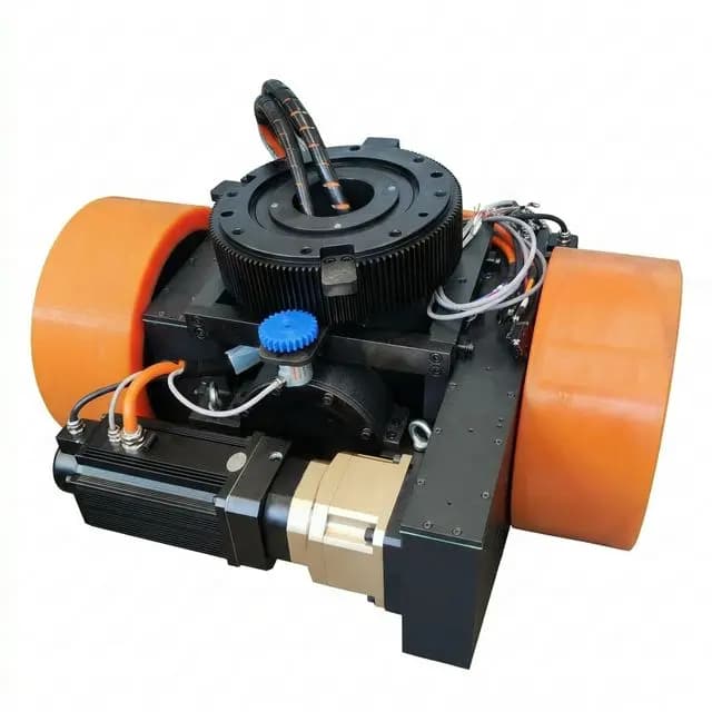
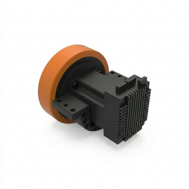
AGV Drive Wheel Dynamic Shock Load Sizing: Expansion Joints, Dock Levelers, Step Drops, and Bearing Brinelling Prevention
Size AGV drive wheels for expansion joints and dock levelers. Compare bearing peak loads, tread profiles and suspension limits, then prepare an engineering RFQ.
For AGV drive wheel shock load sizing, check the peak reaction at each bearing as well as fatigue life. Expansion joints, dock levelers and step drops can load the tire, hub, gearbox and suspension differently. Wheel diameter and a catalogue payload rating alone cannot establish an acceptable crossing speed or prevent bearing brinelling.
This guide is for mechanical engineers, integrators and OEM buyers preparing a drive-unit specification for industrial AGVs and AMRs. It provides a floor survey matrix, reproducible screening arithmetic and an RFQ checklist. If you already have route measurements, send the wheel-load and floor-transition data for an engineering RFQ.
Published and reviewed: 13 November 2026. Scope: global engineering screening for indoor industrial routes. Regional compliance, outdoor operation, cold storage and unusual loads require separate assessment. All numerical examples below are hypothetical calculations, not measured product performance or customer test results. Standards catalogue pages establish document identity and scope; they do not certify a particular vehicle.
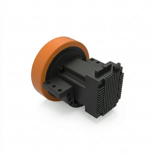
Figure 1: Product illustration of a motorized drive wheel. Internal bearings, tread profile and shock qualification must be confirmed for the quoted model.
1. Floor Discontinuities: Geometric Drop and Impact Dynamics
Separate three events before choosing a load model: bridging an equal-height gap, dropping from one level to another, and climbing a raised lip. A dock plate may also move under load. These events have different contact histories, so adding gap depth and step height into one assumed impact height can misrepresent the excitation.
1.1 Expansion Joint Geometric Drop
For a rigid circular wheel of radius R bridging two sharp, equal-height edges separated by width w, geometry gives the maximum wheel-center lowering. Both edges must support the wheel, and w must be less than the wheel diameter:
h_drop = R - sqrt(R^2 - (w / 2)^2)
h_drop ≈ w^2 / (8 · R) when w is small relative to RFigure 2: Equal-height gap geometry and the load path to a per-bearing capacity check.
For a 200 mm diameter wheel (R = 100 mm), the approximation gives a 0.125 mm drop across a 10 mm gap, 0.500 mm across a 20 mm gap and 1.531 mm across a 35 mm gap. The corresponding exact values are approximately 0.125, 0.501 and 1.543 mm. These numbers describe geometry; they do not classify the shock as harmless or severe.
With a 300 mm diameter wheel, the same 35 mm gap gives an approximate 1.021 mm drop, about one-third lower than the 200 mm wheel result. A larger wheel may therefore help, but packaging, wheel torque, ground clearance and the actual tire deformation also change. The rigid-wheel expression does not cover crumbling edges, resilient fillers, a shallow groove that supports the tread, unequal slab heights or loss of contact at speed.
1.2 What the Classical Drop Formula Can Establish
A common screening model treats a weight W falling a height h onto an initially uncompressed, massless linear spring of stiffness k. Equating gravitational work to spring strain energy gives:
W · (h + x) = 0.5 · k · x^2
delta_static = W / k
K = 1 + sqrt(1 + 2 · h / delta_static)
F_peak = K · W
Here K is a dimensionless force ratio, not an acceleration in g. At zero drop height the model gives K = 2, because it represents sudden application of a weight to an unloaded spring. It does not describe a wheel continuously rolling on a preloaded suspension.
An AGV suspension already carries weight and includes tire damping, unsprung mass, linkage motion and possibly bump-stop contact. Forward speed is absent from this simple equation. The expression cannot set a safe crossing speed, predict a raised-lip collision or serve as a guaranteed upper bound. Use a transient model or instrumented crossing for those decisions; the worked example in Section 6 demonstrates arithmetic and load transfer only.
For two ideal linear compliances in series at the same load coordinate:
k_eff = (k_tire · k_suspension) / (k_tire + k_suspension)A swingarm spring rate must first be converted to wheel rate using its motion ratio. Obtain tire load-deflection curves at the relevant temperature and loading rate. Shore hardness alone does not establish tire stiffness. A suspension that reaches its stop also invalidates a constant series-stiffness assumption.
2. Bearing Brinelling Prevention: Peak Loads and Fatigue Are Separate Checks
A dynamic load rating C supports a rolling-fatigue calculation. A basic static load rating C0 supports a permanent-deformation check, including short shock events while the bearing rotates. A long calculated L10h life therefore does not prove that a hub can tolerate a single dock transition. Shock events also belong in the fatigue duty spectrum when their magnitude and frequency are known.
Figure 3: Schematic comparison of recoverable contact deformation and permanent indentation; not a measured raceway section or a universal stress threshold.
True brinelling is permanent indentation associated with excessive contact loading. Noise, vibration and later surface damage can follow, but the time to failure depends on the bearing, fit, lubrication, contamination and subsequent duty. Similar symptoms can have other causes; inspect the contact pattern rather than diagnosing impact damage from noise alone. False brinelling from small oscillatory motion is a different mechanism and needs a separate diagnosis.
The static safety calculation is:
S0 = C0 / P0
C0_required = S0_target · P0
Use the bearing manufacturer's equivalent static-load method for the exact type and arrangement. For some radial ball bearings, the catalogue form is P0 = max(X0 · Fr + Y0 · Fa, Fr). The coefficients and applicability must be checked in the selected product data. Do not reuse ball-bearing factors for a tapered roller pair or sum two catalogue capacities without an approved arrangement calculation.
Most importantly, Fr and Fa are reactions at the individual bearing. They are not automatically equal to the floor reaction at the wheel. Bearing spacing, wheel overhang, steering moments, axial load allocation and housing stiffness determine the reactions.
SKF's catalogue discussion of static bearing loads and safety factors supports checking peak loads separately from running life. Its guidance varies with bearing type, shock loading and running requirements. Agree the target factor with the supplier for the actual uncertainty and duty. This article's illustrative S0_target = 3 is a project assumption, not an ISO-mandated value for every AGV.
3. Floor Survey Matrix: Measure Before Selecting Hardware
Collect route data in both travel directions and with the actual loaded vehicle. Measure local defects rather than relying on a general floor-flatness report. At a dock, record plate position and trailer movement for the intended operating conditions; an unloaded photograph can miss the limiting transition.
| Transition | Measurements to record | What can change the load path | Engineering decision before release |
|---|---|---|---|
| Armored saw-cut joint | Opening width, edge height, filler condition and route speed | Hard edge contact versus support from filler | Confirm whether a bridging geometry model applies |
| Spalled expansion joint | Maximum opening, damaged edge shape and slab mismatch | Unequal contact points and loose debris | Repair the defect or validate the actual irregular profile |
| Dock leveler entry or exit | Lip height, plate angle, motion and laden wheel load | Drop, climb and plate deflection are distinct events | Qualify the loaded transition in both directions |
| Elevator sill | Gap, level mismatch, door clearance and stopping location | A wheel may stop or restart at the edge | Check traction and recovery as well as transient load |
| Drainage channel or rail crossing | Opening, groove depth, cover strength and approach angle | Bottom contact or cover bending can replace edge bridging | Verify support and cover suitability with the facility owner |
| Outdoor slab step | Step height, broken edges, surface friction and weather | Water, temperature and ground settlement add uncertainty | Establish a separate outdoor envelope before extending an indoor rating |
Do not assign a universal g range from a vehicle class or joint width. Two robots with the same payload can have different wheel reactions because their centers of gravity, casters and suspension layouts differ. Record actual wheel-load distribution for empty, laden, braking and turning conditions before comparing supplier proposals.
4. Polyurethane Tread Geometry: Shoulder Chunking and Trade-Offs
A sharp floor edge can load a small part of a tire shoulder during an angled crossing. Repeated local strain, abrasion, chemical attack or weak core bonding can initiate damage. Examine the failed surface and the route together; shoulder chunking is not proof that one particular polyurethane chemistry or hardness is required.
Figure 4: Qualitative tread-profile concepts. Dimensions and any performance benefit require supplier analysis and comparative testing.
A chamfer can remove a vulnerable shoulder corner. A crown changes the contact patch and may change steering scrub. Both also alter the loaded tread width and pressure distribution, so a proposed profile must be evaluated with the compound, tread thickness and load. No fixed percentage reduction in stress or failures follows from a chamfer dimension alone.
| Profile option | Potential benefit to evaluate | Trade-off or missing evidence | RFQ evidence to request |
|---|---|---|---|
| Flat tread with square shoulder | Broad contact on a level route | Exposed shoulder at oblique edges | Loaded contact pattern and observed damage location |
| Chamfered shoulder | Removes the sharp tread corner | Reduces effective width if oversized | Dimensioned profile and loading limit |
| Rounded shoulder | Smooth transition into the tread | Radius can shift edge pressure | Radius tolerance and comparison under the same load |
| Crowned tread | Changes contact position during steering | Central pressure and heating can increase | Load-deflection, thermal and traction results |
| Dual-taper profile | A different contact progression across the width | Central wear and tracking need checking | Wear pattern and steering behavior on the route |
| Multi-compound tread | Allows investigation of compliance versus support | Bond durability and heat generation need evidence | Material identity, bond qualification and cyclic test results |
Specify performance requirements before selecting a named compound. Request temperature limits, load-deflection behavior, resistance to the facility's fluids, allowable speed and bonding controls. A high Shore hardness or a branded material equivalent alone does not demonstrate impact durability.
5. Gearbox, Suspension and Safety-Scanner Integration
5.1 Gearbox Shock Loads
Keep shaft bending, radial bearing reaction and torque separate. A tangential force at the tread produces wheel-axis torque T = F_t · R. A force directed through the wheel center mainly creates a bearing reaction; multiplying every impact-force magnitude by the radius would overstate torsional demand. Conversely, a wheel jam can produce drivetrain loads that a simple vertical-drop model misses.
Request the reducer's permitted peak and emergency torque, pulse duration, repetition count, output radial and axial limits, and the mounting geometry used for those limits. Planetary and cycloidal architectures each need model-specific evidence. Neither name establishes a universal overload percentage. Compare the load path and integration constraints in the planetary versus cycloidal AGV drive wheel gearbox guide, then verify the selected supplier's current ratings.
5.2 Spring Rate, Travel and Damping
For a single linear mode, damping ratio is zeta = c / (2 · sqrt(k · m)), with all terms expressed at the same coordinate. Critical damping is zeta = 1; values such as 0.5 to 0.7 are underdamped. A real chassis has multiple coupled modes, and one ratio cannot guarantee scanner alignment or wheel contact.
Choose preload, usable travel, rebound control and damping together. Verify that the laden system does not bottom out, that the light vehicle retains traction and that repeated crossings do not overheat the tire or damper. The AGV drive wheel suspension comparison provides layout context. It does not replace a transient assessment of your chassis.
5.3 Scanner Stops and Vehicle Safety
Pitch and roll can change the scanner plane. As a geometric illustration, a scanner 0.15 m above a level floor pitched downward by 2 degrees intersects that floor at approximately 0.15 / tan(2 degrees) = 4.30 m. Actual protective-field shape, mounting and diagnostics determine whether that causes a stop. A protective stop must not automatically be described as a Category 0 emergency stop.
ISO 3691-4:2023 addresses safety requirements and verification for driverless industrial trucks and their systems, including the importance of the operating zone. Use the applicable edition and the scanner manufacturer's instructions in the vehicle assessment. This guide does not claim a mandatory pitch limit, test-cylinder size or damping ratio from the public catalogue abstract. Resolve mechanical disturbances without disabling protective functions.
6. Worked Sizing Example: From Wheel Impact to Bearing Reaction
This hypothetical example combines an ideal drop-spring calculation with a simple overhung hub model. It is reproducible screening arithmetic, not a qualification of an AGV or a recommendation to operate at the specified defect. No bearing part number, measured tire stiffness or validated approach speed is implied.
6.1 Assumed Inputs and Idealized Peak Force
Assume W = 16,000 N supported by one wheel, a 250 mm wheel diameter, a 12 mm drop, tire stiffness 14,000 N/mm and suspension wheel rate 1,200 N/mm. These stiffnesses are invented example inputs; they must be replaced by supplier data. The drop calculation uses the initially uncompressed spring model from Section 1.2, not a simulation of a preloaded vehicle.
k_eff = 14,000 · 1,200 / (14,000 + 1,200)
      = 1,105.263 N/mm
      = 1.105263 × 10^6 N/m
delta_static = 16,000 / 1,105.263 = 14.476 mm
K = 1 + sqrt(1 + 2 · 12 / 14.476) = 2.630305
F_peak = 16,000 · K ≈ 42,085 N
The model requires approximately F_peak / k_eff = 38.1 mm total elastic deflection at its peak. That is not automatically suspension stroke: the tire and suspension have different shares, and real preload changes the available travel. Check each element and the stops explicitly before using an effective stiffness.
6.2 Resolve the Overhung Bearing Reactions
Assume two ideal radial supports spaced L = 100 mm apart, with the wheel-force plane overhanging the nearer support by e = 30 mm. Ignore shaft and housing flexibility for this demonstration. Equilibrium gives:
R_near = F_peak · (1 + e/L) ≈ 54,710 N
R_far  = -F_peak · e/L      ≈ -12,625 N
R_near + R_far = F_peak
The negative sign indicates the far support's opposite reaction direction; use its magnitude for its radial load check. The nearer bearing sees about 30% more radial load than the wheel reaction. This is why simply dividing wheel force equally between two bearings can miss the governing component.
Suppose a separate lateral-load assessment assigns Fa = 10,000 N to the near locating bearing. This is another assumed input. An oblique floor-crossing angle alone does not justify calculating axial force as F_peak · sin(angle).
6.3 Apply a Catalogue Method and an Explicit Project Target
For demonstration only, assume the selected radial ball bearing's catalogue specifies X0 = 0.6, Y0 = 0.5 and the radial-load floor shown below:
Fr = abs(R_near) ≈ 54,710 N
P0 = max(0.6 · Fr + 0.5 · Fa, Fr)
   = max(37,826 N, 54,710 N)
   = 54,710 N
S0_target = 3.0   (illustrative project choice)
C0_required = 3 · 54,710 ≈ 164,000 N = 164 kN
A hypothetical candidate with C0 = 180 kN gives S0 ≈ 3.29 for this check. That does not approve its dynamic life, fit, clearance, speed, shaft, housing, seals or the complete drive unit. Check the far bearing and all other load cases separately. A roller-bearing alternative requires its own catalogue coefficients and arrangement model.
For a supplier comparison, attach the force assumptions, hub drawing, wheel overhang, accepted safety factor and unresolved measurements. If actual loads are uncertain, agree an instrumented test and acceptance conditions rather than presenting the calculated capacity as a certified wheel rating. Submit those inputs with your engineering RFQ so proposals use the same basis.
7. Pre-Procurement and RFQ Verification Checklist
Use this checklist to make supplier answers comparable. A quote with a large payload number but no load path or test conditions leaves the most important questions open.
- Route envelope: Provide measured gaps, steps, edge condition, crossing angles, directions and planned speeds, including loaded dock positions.
- Wheel loads: State empty and laden wheel reactions, center-of-gravity changes, braking, turning and unequal load sharing.
- Bearing arrangement: Request part identities,
CandC0, spacing, overhang, preload or clearance, fits and the equivalent-load method for each bearing. - Acceptance factors: Record who selected
S0_target, why it suits the duty and how load uncertainty is treated. Keep fatigue-life and peak-load checks separate. - Tire evidence: Request a dimensioned tread profile, compound identity, load-deflection curves, temperature and speed limits, and core-bonding controls.
- Reducer and mounting: Obtain permitted torque pulses, output bearing limits, mounting loads and encoder installation requirements for the exact model.
- Suspension limits: Document wheel rate, motion ratio, preload, usable bump and rebound travel, damping, stop contact and traction at minimum load.
- Test definition: Specify pulse shape, acceleration, duration, axes, repetitions, mounting, operating state and post-test inspections. Agree how laboratory exposure relates to the route.
- Vehicle acceptance: Record crossing runs, wheel contact, scanner diagnostics, temperature, vibration and inspection results against agreed criteria before release.
IEC 60068-2-27:2008 provides a shock-test method. It does not give every AGV drive an automatic rating of 25 g for 11 ms. A motor or encoder test also does not establish assembly durability. Request the actual report and confirm that its mounting and severity represent the failure mechanism being evaluated.
8. Frequently Asked Questions
Why can bearings fail despite a long calculated L10h life?
A fatigue-life calculation and a peak-load check address different damage mechanisms. Short impacts can cause permanent raceway indentation even when the running-load fatigue calculation looks acceptable. Include shocks in the duty spectrum and check each bearing’s equivalent static load, fits, lubrication and mounting. A calculated life is not a guaranteed service interval.
How large a floor joint or step drop can an AGV drive wheel safely cross?
There is no universal safe gap-to-diameter ratio. For equal-height sharp gap edges, the rigid-wheel geometric drop is R minus sqrt(R squared minus (w/2) squared). That calculation does not approve speed, traction or a raised step. Measure the actual transition and validate the complete loaded vehicle within the manufacturer’s operating envelope.
What is the difference between dynamic rating C and static rating C0?
C supports bearing fatigue-life calculations under a specified load spectrum. C0 supports a separate check of permanent contact deformation under peak loads. Calculate S0 = C0/P0 for each bearing using its catalogue method and supplier-agreed acceptance factor. S0 = 3 in this article is an illustrative project choice, not a universal ISO requirement.
Can a chamfered or crowned tire prevent shoulder chunking?
A shoulder chamfer or crown can change where a joint edge contacts the tread, but neither guarantees freedom from chunking. Select dimensions with the tire supplier and validate loaded width, contact pressure, traction, heat buildup, compound properties and core bonding. No fixed percentage improvement is claimed without comparative test data.
Why can floor transitions cause safety-scanner stops?
Chassis pitch or roll can change the scanner plane and cause a protective field to intersect the floor. Log scanner diagnostics and correlate them with measured vehicle attitude before assigning the cause. The resulting stop category depends on the safety system. Do not suppress protective functions to hide a mechanical problem.
What suspension spring and damping ratio should an AGV use?
Choose spring rate, preload, travel and damping together for the actual supported mass, linkage motion ratio and floor excitation. A damping ratio below one is underdamped; critical damping is one in the ideal linear model. Validate wheel contact, bump-stop clearance and vehicle pitch rather than treating one ratio or travel multiple as a universal solution.
Can software speed zones replace mechanical load checks?
Speed reduction can reduce some impact excitation, but forward kinetic energy is not identical to vertical impact energy. Gravity drops, moving dock plates and operating-mode changes still need analysis. Validate the permitted crossing speed together with wheel, bearing, suspension and vehicle limits, and document how that speed is enforced.
What evidence should an encoder shock report contain?
Request the exact sensor and mounting identity, shock pulse shape, acceleration, duration, axes, repetitions, operating state and pass criteria. A component-level shock rating does not qualify the complete drive assembly. Select any coupling or isolation mount against alignment and resonance requirements; magnetic sensing alone does not establish shock immunity.
9. Prepare a Drive-Unit Selection Review
Start with the route and wheel-load envelope, resolve bearing reactions from the hub geometry, and compare peak-load, fatigue, tire and reducer limits separately. Keep assumed values visible until measurement or supplier evidence replaces them. A floor repair or a revised crossing speed may be more practical than increasing every component size.
Use the Heavy Load Forklift AGV Wheel Selector for preliminary vehicle inputs, and the AGV Forklift Steering Drive Wheel selection page for steering integration questions. Neither tool establishes a shock qualification. For a model-specific review, send your route survey, hub layout and duty cycle with an RFQ.
10. Sources and References
Sources checked on 13 November 2026. The example arithmetic and qualitative decision tables are editorial engineering aids. They are not empirical measurements or published universal operating limits.
- SKF rolling bearings catalogue, printed pages 14 and 19–20 (PDF pages 16 and 21–22): static bearing loads, permanent deformation, separate fatigue and peak-load checks, and application-dependent static safety-factor guidance. This is a reference catalogue; confirm ratings for the exact current product. Read the SKF catalogue.
- ISO 3691-4:2023, Industrial trucks — Safety requirements and verification — Part 4: Driverless industrial trucks and their systems. The public catalogue supports document identity and scope; a full vehicle assessment requires the applicable text and regional requirements. View the ISO catalogue record.
- IEC 60068-2-27:2008, Environmental testing — Part 2-27: Tests — Test Ea and guidance: Shock. Defines the shock-test procedure and selection of representative exposure; severity and acceptance criteria must be specified for the tested assembly. View the IEC catalogue record.