Horizontal vs. Vertical AGV Drive Wheels: Footprint, Clearance, and OEM Sourcing Guide
Compare horizontal and vertical AGV drive wheels for chassis height, swept clearance, cable routing, and supplier evidence. Prepare an OEM engineering RFQ.
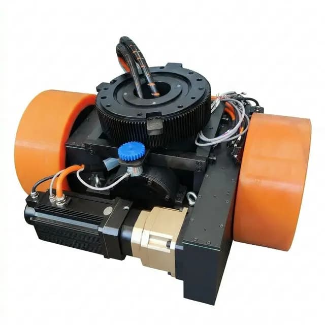
When engineering a steerable AGV drive wheel for an automated guided vehicle (AGV) or autonomous mobile robot (AMR), the first packaging decision is often horizontal versus vertical traction motor orientation. A horizontal layout can save chassis height while consuming more space around the steering pivot. A vertical layout can reduce that lateral envelope while requiring more headroom. Neither label establishes a wheel load rating, efficiency advantage or safety approval.
Scope and review date: Global / English, 25 October 2026. This guide is for OEM chassis engineers and procurement teams comparing steerable traction modules. It provides an analytical screening method, not measured product benchmarks. The schematic and numerical example are illustrative; dimensions, duty ratings and prices require a model-specific drawing and quotation. Local requirements and the applicable standard edition must be confirmed for the vehicle and destination market.
Choosing the wrong envelope can force a chassis redesign: a low horizontal motor may strike a battery bracket when it steers, while a vertical tower may exceed an underride cart's available height. Check both constraints before comparing motor power or unit price.
If you are already comparing supplier drawings, use our AGV forklift steering wheel selection calculator and report or send your payload, available height and wheel-well dimensions to our engineering team for an initial technical review.
1. Architectural Anatomy: Horizontal vs. Vertical Modules
A steerable drive wheel combines several functions. Their integration varies by supplier:
- Traction motor: Provides propulsion, often through a BLDC or permanent-magnet synchronous motor.
- Steering mechanism: Turns the wheel assembly through a bearing and reduction stage; its permitted travel may be bounded.
- Transmission: Converts motor speed to wheel torque through the selected gear arrangement.
- Brake: May provide parking or holding duty. Dynamic emergency braking capability must be separately specified and verified.
- Feedback: Measures traction speed and steering angle. Encoder channel count alone does not establish a safety function's performance level.
1.1 Horizontal Configuration: Height First
The traction motor lies approximately parallel to the floor. Depending on the motor-to-axle arrangement, the transmission may use parallel-axis gears or an angle-changing stage; horizontal motor orientation does not require a bevel gearbox.
Packaging advantage: A low motor position can help a steerable module fit an underride chassis. Constraint: If the motor turns with the wheel and extends away from the steering axis, its housing, brake, connectors and cables need lateral clearance throughout the permitted steering range.
1.2 Vertical Configuration: Wheel-Well Footprint First
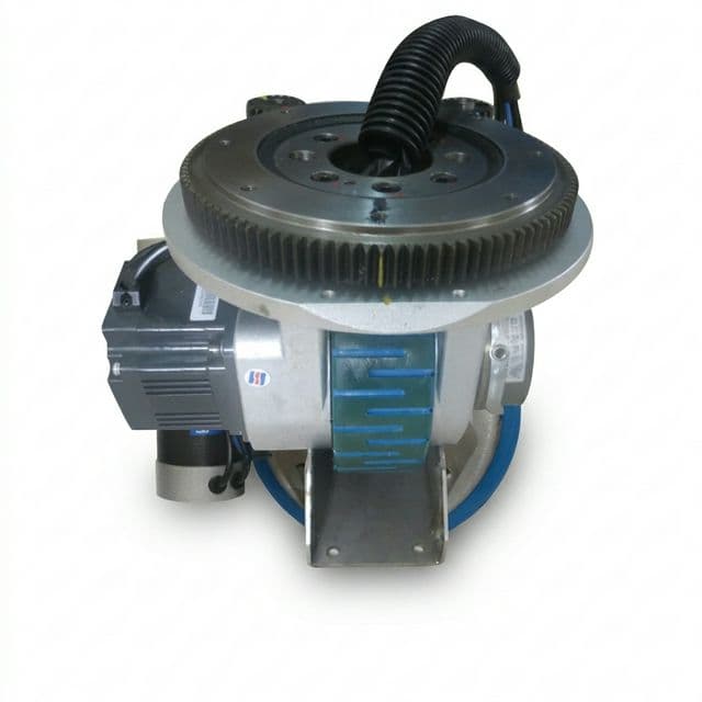
The traction motor stands approximately upright, along or beside the steering column. The transmission must connect the vertical motor shaft to the horizontal wheel axle; a planetary reduction stage alone does not turn that axis through 90 degrees.
Packaging advantage: Concentrating components above the wheel can reduce the rotating footprint and may allow top service access. Constraint: The complete tower, connectors, steering motor and removal path need headroom. Off-axis housings can still project outside the steering bearing diameter, and bearing loads depend on geometry rather than the orientation label.
2. Technical Comparison Matrix: Engineering & Sourcing Dimensions
Use these ten dimensions to screen supplier proposals. These are conditional layout tendencies, not catalogue ranges or guaranteed performance differences.
| Engineering Dimension | Horizontal Drive Wheel Module | Vertical Drive Wheel Module | Design & Procurement Evidence |
|---|---|---|---|
| Chassis height | Can suit a low deck or underride platform | Requires space above the wheel | Dimensioned assembly drawing, connectors and suspension travel |
| Steering swept envelope | Offset rotating motor may enlarge the footprint | A centered tower may keep the footprint compact | STEP model checked at every permitted angle and relevant height |
| Wheel diameter | Packaging may constrain tire choice | Tower packaging may allow a different wheel size | Actual wheel diameter, worn radius and obstacle requirements |
| Wheel load capacity | Depends on tire, bearings, frame and duty | Depends on the same components and duty | Per-wheel static and dynamic ratings, distinct from vehicle payload |
| Overturning moment | An offset motor can add a gravity moment | A centered motor may reduce that contribution | Bearing load/moment envelope and wheel-to-bearing offsets |
| Cable management | A flex loop must clear the rotating housing | A central route may be possible | Validated travel, bend radius, torsion and rotary-interface ratings |
| Mechanical efficiency | Depends on gearing, lubrication and operating point | Depends on gearing, lubrication and operating point | Comparable input/output measurements across the duty cycle |
| Ingress exposure | Low housings may encounter splash and debris | Elevated components may see less floor splash | Enclosure, connector and seal test scope for the real environment |
| Service access | May need an underside access opening | May permit top removal if the deck allows it | Demonstrated brake, motor and tire replacement procedure |
| BOM and lifecycle cost | Installation and cable support affect total cost | Tower integration and service access affect total cost | Like-for-like quote, spares, lead time and maintenance assumptions |
For high wheel loads, compare the supplier's duty-specific evidence with our heavy-duty AGV drive wheels guide. A vehicle payload rating is not a single-wheel rating.
3. Geometric and Kinematic Deep Dive
3.1 Swept Radius: A Reproducible Packaging Screen
For a simplified rectangular motor housing rotating with the steering assembly, assume that its centerline extends radially outward from the pivot. Let D_pivot be the nonnegative distance from the steering axis to the motor's near face, L_motor its length including the brake, and W_motor its width. An outer-corner screen is:
R_sweep = sqrt((D_pivot + L_motor)^2 + (W_motor / 2)^2) + deltadelta is a project-specific clearance allowance for tolerances and deflection. It is not a safety distance prescribed by a standard. If the motor is offset sideways, the near face crosses the pivot, or other parts project farther out, calculate all relevant corner distances from the actual CAD coordinates instead.
Hypothetical worked example, all dimensions in millimetres:
L_motor = 220; D_pivot = 60; W_motor = 110; delta = 20
R_sweep = sqrt(280^2 + 55^2) + 20
        = 285.3507 + 20 = 305.3507 mm
Full-rotation diameter = 610.7014 mm; round outward to 611 mm
This is a conservative 2D screen for that example's motor outline, not a measured 750 W product specification or a requirement for every horizontal unit. With full rotation, any chassis feature at the motor's height must clear the applicable envelope. A circular hole through the entire chassis is not necessarily needed: parts can occupy other heights, and bounded steering can reduce the required sector. Include the gearbox, wheel, cable loop, connector backshells and suspension travel in the final 3D check.
Do not confuse this internal module sweep with the vehicle's aisle turning radius. The latter also depends on module location, wheelbase, steering topology, chassis corners and payload overhang. A compact vertical module can still sit in a vehicle with a large turning envelope.
3.2 Ground Clearance, Ramps and Protective Fields
Loaded tire deflection, suspension travel, wheelbase, overhangs and ramp transitions determine whether a housing can strike the floor. Check both empty and loaded configurations against the route profile; motor orientation alone cannot establish an allowable ramp angle or minimum ground clearance.
ISO 3691-4:2023 addresses driverless industrial trucks and their systems. Its public catalogue record confirms scope, not a universal skirt-clearance number or an approved scanner field for this design. Determine foot protection, stopping behavior and protective fields from the applicable requirements and vehicle risk assessment. If a rotating module can project beyond the body, include that reachable contour in the assessment.
Before freezing the battery tray, send the permitted steering range, envelope drawing and ramp profile for an engineering review.
4. Visual Comparison: Structural Layout & Clearance Profiles
The following conceptual schematic shows the packaging trade-off. It is not to scale and does not specify a product's dimensions, bearing capacity or required gearbox arrangement.
Mechanical Layout Comparison: Vertical vs. Horizontal AGV Drive Wheels
5. Cable Management: Bounded Rotation vs. Rotary Interfaces
First establish which devices rotate and where their controllers are mounted. The steering joint may carry motor phase conductors, brake power, encoder signals, temperature signals or a DC supply and communications link to a rotating controller. Battery voltage does not directly specify motor phase voltage or current.
5.1 Bounded Rotation with Flexible Cables
A cable loop or guided cable carrier can support a finite angle range. Specify the actual motion, cable length, bend radius, torsion per unit length, cycle profile and temperature. Supplier cycle claims are useful only when the test conditions match the installation; a flex cable does not guarantee error-free communications.
The controller needs a defined response near the travel limit, including an unwind strategy where required. Software limits, mechanical stops and any safety-related limit detection must be designed together. A complete 360-degree travel range is different from unlimited repeated rotation.
5.2 Unlimited Steering with a Rotary Interface
Unlimited rotation requires a suitable transfer method for every connection crossing the joint, such as a rated slip ring or contactless rotary interface. Check continuous and peak current, thermal rise, insulation, shielding, communication protocol, environmental rating and service life. Some vehicle motions, including crab motion, can be achieved with bounded steering; unlimited rotation is a separate requirement.
Vertical shafts may offer a central route, while horizontal layouts may need routing around the offset gearbox. Neither guarantees easier integration. Evaluate electrical noise under real PWM drive and steering operation rather than selecting by contact material alone.
For the vehicle-level relationship between steering and positioning, see our AGV navigation method selector.
6. Load Paths, Overturning Moments, and Bearing Evidence
A steering bearing transfers chassis loads into the wheel assembly while allowing steering. Both layouts can experience axial load, radial load and overturning moments. A vertical motor does not eliminate wheel offset, braking-force lever arms or chassis deflection.
6.1 Separate the Load Contributions
For an initial free-body diagram, a motor mass offset from the steering axis contributes a gravity moment of magnitude:
M_motor = m_motor * g * L_offsetA horizontal traction or braking force contributes a moment based on its perpendicular distance to the bearing load reference plane:
M_force = F_horizontal * hWheel torque F_traction * R_wheel is a different quantity; it is not by itself the steering bearing's overturning moment. Account for force directions, contact-patch offsets, load transfer, floor impacts and support geometry when combining loads.
6.2 Request a Duty-Specific Bearing Assessment
Ask the supplier for its allowable combined load/moment envelope, mounting stiffness assumptions, duty spectrum and lubrication requirements. Limited-angle oscillation and impact service may require checks beyond a nominal rolling-bearing life calculation. Do not infer operating hours, bearing type or replacement interval solely from motor orientation.
Compare the mounting and floor-following assumptions with our AGV drive wheel suspension systems guide.
7. Application Suitability: Screen Constraints Before Vehicle Labels
7.1 When to Shortlist a Horizontal Layout
- Underride cart movers: Available height rules out a tower, and the complete rotating module still fits laterally.
- Low-deck steerable platforms: The frame can reserve space for motor sweep, cable routing and service removal.
- Height-constrained process carriers: The chosen assembly meets loaded clearance and thermal duty requirements.
Many low-profile AMRs use differential or other non-steerable architectures. Being an underride robot does not make a horizontal steerable module mandatory.
7.2 When to Shortlist a Vertical Layout
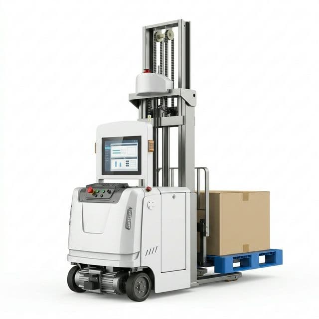
- Automated forklifts: Headroom and a narrow wheel well favor the tower, subject to actual wheel loads and mounting evidence. See our forklift AGV solutions for platform context.
- Industrial tuggers: The package fits and the tire, drive and bearing meet drawbar-force, traction and braking requirements. Towed mass alone is insufficient for sizing.
- Mobile manipulators or dual-steer platforms: A compact module footprint helps packaging, but steering acceleration still depends on inertia, friction, steering torque and controller limits.
For each proposal, reject any unresolved height or collision constraint first. Then compare load and thermal duty, steering/cable limits, service access and total quoted scope. This sequence prevents a favorable motor-power or unit-price figure from hiding a packaging failure.
8. Sourcing & Engineering RFQ Checklist
Use the following checklist to make horizontal and vertical proposals comparable:
- Chassis envelope: Provide maximum installed height, mounting datums, permitted steering range, swept 3D envelope, suspension travel and a justified clearance allowance.
- Wheel load and duty: Separate vehicle gross mass, payload and worst-case per-wheel load. Include the specified acceleration, braking, route gradient and impact assumptions.
- Cable or rotary interface: State finite travel or unlimited rotation; request bend/torsion limits, current ratings, cycle conditions and an unwind strategy where applicable.
- Electrical compatibility: Confirm battery range, controller placement, motor phase requirements, brake supply, feedback protocol, EMC measures and connector pinouts.
- Ground clearance: Check tire wear/deflection, empty and loaded configurations, ramp crests, dock transitions and housing overhangs using the route geometry.
- Environment: Specify dust, splash, jets or immersion exposure and cleaning chemicals. Request evidence for seals, connectors and the complete enclosure, not just a motor IP label.
- Braking: Request holding and dynamic-stop capabilities separately at the actual load, slope, temperature and duty. Do not size a vehicle brake from a universal percentage of rated motor torque.
- Safety functions: Identify the required functions and performance levels from applicable vehicle requirements and risk assessment. Request system integration and validation evidence; two encoder channels alone do not establish PL d or SIL 2.
- Service and acceptance: Confirm safe isolation/support, motor, brake and tire removal paths, spare-part availability, warranty, sampling lead time and agreed acceptance criteria.
ISO 13849-1:2023 provides a design methodology for safety-related control systems. It does not itself prescribe the safety functions or required performance levels for every application. Confirm the applicable vehicle requirements before specifying an encoder or steering-limit solution.
For commercial terms and a quote-ready structure, use our AGV drive wheel RFQ checklist for OEM buyers.
9. Frequently Asked Questions (FAQ)
What is the primary difference between horizontal and vertical AGV drive wheels?
The labels describe the traction motor orientation relative to the floor. Horizontal layouts can reduce module height but may need more space around the steering pivot. Vertical layouts can concentrate the motor above the wheel but need headroom. Confirm both envelopes from the selected supplier drawing; orientation alone does not establish load capacity.
Can a horizontal AGV drive wheel steer continuously through 360 degrees?
Yes, if every connection crossing the steering joint supports unlimited rotation, for example through a suitably rated slip ring or rotary interface. A cable loop provides bounded steering and needs a validated angle range, bend radius and unwind strategy. Vehicle crab motion does not by itself require unlimited steering rotation.
Are vertical drive wheels always better for automated forklifts?
No. A vertical layout is worth screening when headroom is available and a compact wheel well or top service access matters. Approve the actual wheel load, bearing moment rating, brake performance and mounting arrangement. Motor orientation does not eliminate overturning loads or establish forklift capacity.
Which drive wheel layout is quieter or more efficient?
Neither orientation guarantees lower noise or higher efficiency. Compare the complete transmission, motor operating point, controller, mounting stiffness and tire under the same load and speed. Request supplier test conditions and measured results rather than accepting an orientation-based ranking.
Does an IP67 drive wheel rating establish washdown suitability?
No. Request the enclosure test scope, connector and shaft-seal coverage, and evidence for the actual cleaning method, temperature and chemicals. State any jet and immersion requirements separately. Mounting the motor higher may reduce exposure but does not establish washdown or hygiene suitability.
For related tire failure mechanisms and supplier questions, see our polyurethane delamination guide for 24/7 AGV drive wheels.
10. Conclusion and Next Steps
Shortlist horizontal drive wheels when height is the binding constraint and the verified motor/cable sweep fits. Shortlist vertical drive wheels when headroom is available and a compact wheel well or top service path is valuable. Approve the specific assembly only after checking loads, transmission duty, clearances, electrical interfaces and vehicle safety requirements.
To move from a layout preference to a comparable supplier proposal:
- Review our AGV forklift steering wheel modules and warehouse logistics AGV solutions.
- Request available STEP/IGES models, dimensional drawings and integration guides through our engineering resources; availability depends on the wheel series.
- Send your load profile, chassis envelope, steering range and floor conditions to our engineering team for an initial layout and RFQ review.
11. Sources and References
The following primary-source catalogue records were checked on 25 October 2026. They establish the identity and scope of the referenced standards; they do not supply orientation-specific dimensions, efficiency, price or lifetime benchmarks. Clause-level design decisions require the applicable full standard and vehicle assessment.
- ISO 3691-4:2023 — Industrial trucks: Safety requirements and verification, Part 4: Driverless industrial trucks and their systems. Vehicle and system safety scope; not a universal module-clearance approval. ISO catalogue record.
- ISO 13849-1:2023 — Safety of machinery: Safety-related parts of control systems, Part 1: General principles for design. Methodology for safety-related control system design and integration. ISO catalogue record.
- IEC 60529:1989+A1:1999+A2:2013 — Degrees of protection provided by enclosures (IP Code), consolidated edition 2.2. Enclosure protection classification; obtain evidence for the selected assembly and exposure. IEC catalogue record.