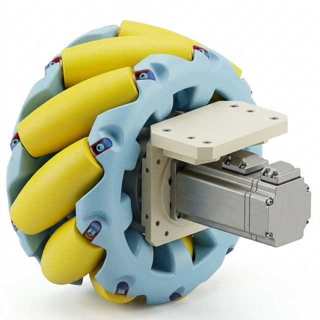
310mm Mecanum Wheel Forklift Adaptation: What to Check
For forklift OEMs, system integrators, and fleet engineering teams evaluating a 310mm mecanum wheel adaptation, use this preliminary screen to compare stated load and route inputs with transparent heuristics, then identify the drawings, approvals, and test evidence still needed.
Screening aid only: equal load share and unvalidated floor, ramp, clearance, and calibration heuristics are assumptions. This tool does not confirm component fit, rated capacity, stability, or compliance. Verify drawings and written approvals, then validate the vehicle before use.
10 public sources checked on 2026-10-01
Forklift approval and load-center checks
3 open evidence questions with closure requirements
First published 2026-05-03 · Last reviewed 2026-10-01
Empty state: run the checker to generate your 310mm adaptation result.
Pre-filled demonstration inputs appear below; they are not a conservative or validated forklift specification.
Drive-axle mass
2,604 kg
Modeled load estimate per wheel
1,291 kg
Modeled load / entered rating
143.4%
Diameter delta
5.2 mm
Heuristic clearance score
0 / 100
Heuristic slip band
High (Radius checked; chassis geometry partly verified)
The selected assumptions exceed this screen’s modeled load or clearance boundary. Escalate for engineering review; this result is not a finding that any specific wheel or forklift is safe or unsafe.
310 mm equals 310.0 mm (12.20 in). Baseline comparison uses 304.8 mm (12 in exact).
Report Summary: Decision Snapshot
Updated 2026-10-01Selected assumptions exceed this screen’s modeled load or heuristic clearance boundary
Fixed heuristic from wheel count, floor, calibration, ramp, and modeled utilization; not a statistical confidence estimate.
Uses 304.8 mm baseline and exact inch-mm conversion anchor
Relative indicator for route stress and slip propensity
- Indoor forklift platforms with known floor quality and measurable duty cycle.
- Teams needing a rapid go/pilot/redesign decision before detailed RFQ.
- Integration workflows that can provide controller geometry calibration evidence.
- Scenarios expecting compliance sign-off from this page without formal safety process.
- Outdoor or highly variable routes where floor and traction statistics are unknown.
- Profiles with severe overload or tight clearance that require immediate architecture redesign.
Evidence gates before adapting a 310mm wheel
A diameter match is only the first screen. Close these forklift-specific fit, approval, commissioning, and route evidence gates before ordering or releasing the retrofit.
| Adaptation gate | Evidence to collect | Release check |
|---|---|---|
| Wheel-to-chassis interface | Current and candidate drawings for hub bore, key/keyway, bolt pattern, offset, fasteners, and side envelope. | Approve a dimensioned adapter model with tolerance stack and measured clearance. |
| Capacity and load center | Forklift capacity plate, attachment/load-center configuration, and the candidate wheel maker’s model-specific rating. | Obtain written manufacturer approval and updated capacity markings before procurement release. |
| Kinematics and commissioning | Loaded wheel radius, roller orientation, chassis lx/ly geometry, encoder direction, and pinned controller configuration. | Record commissioning values and verify low-speed route replay before production sign-off. |
| Route pilot | Representative payload, floor joints, ramps, shift duration, wheel current, temperature, slip events, and route shocks. | Set project-specific stop and pass thresholds before the pilot; compare measured results with those thresholds. |
Methodology and Evidence
1) Drive-axle mass = gross mass x drive-axle share; equal load share across driven wheels is assumed.
2) Modeled load estimate = static load x selected floor factor x (1 + 0.02 x ramp percent) x user-selected multiplier.
3) Modeled utilization = load estimate / user-entered per-wheel rating.
4) Screening band combines modeled utilization and unvalidated clearance/slip heuristics. It is not a fit, safety, or compliance verdict.
Route-demand proxy = gross mass x (floor rolling factor + ramp ratio) x (1 + daily distance / 100). It is an unvalidated relative index, not traction force, motor torque, or a rated performance value.
Screening confidence is low for six driven wheels, rough floors, uncalibrated geometry, modeled utilization above 95%, or ramps at/above 10%; medium for jointed floors, partial calibration, utilization above 80%, or ramps at/above 7%; otherwise it is high. This is a fixed flag, not a statistical confidence interval.
Band logic: redesign review at utilization above 100% or clearance score at/above 80; pilot review for high slip, ramps at/above 10%, utilization above 85%, or clearance score at/above 55; interface/load review for medium slip, utilization above 65%, or clearance score at/above 35; six-wheel lower bands are raised to pilot review; lower concern otherwise.
Slip score = floor base (16/28/42) + 3 x ramp percent + 0.35 x modeled utilization percent + calibration penalty (0/7/15). Bands are below 65, 65-94, and 95 or higher; no field-validated slip thresholds are claimed.
Clearance score uses max(90 mm, 30% of wheel diameter) as a heuristic need, then clamps the clearance shortfall plus 1.8 x ramp percent to 0-100. It is not a geometric clearance calculation.
These factors and the 1.3/1.5/1.8 multipliers are screening assumptions, not values from a wheel rating, test report, standard, or engineering approval. Use a supplier/OEM load model and measured vehicle data for decisions.
| Assumption | Default | Boundary note |
|---|---|---|
| Baseline diameter | 304.8 mm (12 in) | Exact unit anchor; fit still depends on tolerance stack |
| Ramp factor | 1 + ramp% x 0.02 | Conservative approximation for pre-screen only |
| Grade governance threshold | >10% loaded grade | 1910.178 requires load-upgrade handling; route to pilot-level controls |
| Floor dynamic factors | 1.08 / 1.18 / 1.32 | Unvalidated screening assumption; replace with route measurements |
| Controller scope baseline | 4-wheel mecanum reference stack | 6-wheel layouts require custom kinematics validation |
| Safety factor options | 1.3 / 1.5 / 1.8 | User-selected screen multiplier; not a prescribed safety factor |
| Source | Decision use |
|---|---|
| NIST Handbook 44 Appendix C (2026) 2026 edition PDF, checked 2026-10-01 | NIST lists 1 inch = 2.54 cm exactly and 1 foot = 0.3048 m exactly, anchoring 310 mm = 12.20 in class conversion. Conversion is exact, but interchangeability still depends on hub geometry and tolerance stack. |
| eCFR 29 CFR 1910.178 (current text) eCFR live text checked 2026-10-01 | 1910.178(a)(4) requires prior written manufacturer approval for modifications affecting capacity/safe operation; 1910.178(q)(6) restricts added counterweighting without manufacturer approval. Regulation sets governance gates and minimum practices, not wheel-by-wheel life prediction. |
| OSHA interpretation letter on 1910.178(a)(4) Issued 1997-04-11, corrected 2009-04-07, checked 2026-10-01 | If manufacturer is unavailable or gives no response, OSHA states a Qualified Registered Professional Engineer can provide written approval with safety analysis. This is a fallback pathway, not a shortcut to bypass engineering diligence or nameplate updates. |
| eCFR 1910.178 traveling and maintenance clauses eCFR live text checked 2026-10-01 | 1910.178(n)(7) requires slow grade travel, 1910.178(n)(7)(i) specifies load-upgrade driving on grades over 10%, and 1910.178(q)(7) requires at least daily inspections (or per shift for round-the-clock use). Operational controls reduce incident probability but cannot salvage an overload design. |
| OSHA 1910.178 App A stability guidance OSHA page checked 2026-10-01 | Appendix A states many trucks <=30,000 lb are rated at a 24 in load center and gives a worked example: 3000 lb at 24 in => 72,000 in-lb, dropping to 2400 lb allowable at a 30 in load center. Appendix A is non-mandatory guidance, but it provides a transparent load-moment reasoning baseline for pre-screening. |
| ROS2 mecanum_drive_controller user documentation Rolling docs (Sep 2026) checked 2026-10-01 | Controller scope is four mecanum wheels; parameters include wheels_radius > 0 and lx+ly geometry. reference_timeout resets stale velocity commands. Controller math quality cannot compensate for unsafe mechanical envelopes. |
| ROS package API docs for mecanum_drive_controller Rolling API release snapshot 6.6.0 from 2026-05-03; link checked 2026-10-01 | The rolling package explicitly describes the implementation as a 4-wheel mecanum controller and publishes rapid 2026 release cadence (6.5.0 on 2026-04-02, 6.6.0 on 2026-04-22). Behavior may shift across minor releases, so project teams should pin tested controller versions. |
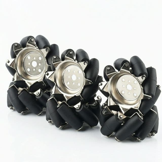
| WPILib MecanumDrive API (2026.2.2) WPILib API 2026.2.2 checked 2026-10-01 | Describes the canonical four-corner mecanum layout and states roller axles should form an X pattern. This is a kinematic/orientation reference, not an industrial durability or compliance standard. |
| NEXUS NM305A product page (official) Vendor page checked 2026-10-01 | NM305A is published as a 305 mm class wheel with 3000 kg/set headline capacity. Set-level headline rating does not include duty cycle, route shock, or thermal assumptions. |
| NEXUS NM305B product page (official) Vendor pages checked 2026-10-01 | NM305B is also 305 mm class, but published at 2000 kg/set headline capacity. Diameter class match does not imply identical capacity or lifecycle behavior. |
| Decision question | New data point | Boundary | Action | Sources |
|---|---|---|---|---|
| Can 310 mm be treated as a 12 inch class input in tool formulas? | NIST Handbook 44 Appendix C publishes exact inch-foot metric anchors (1 in = 2.54 cm exact; 1 ft = 0.3048 m exact), placing 310 mm in a 12.20 in class. | Exact conversion does not eliminate mechanical stack-up from hub bore, offset, and roller envelope. | Use 310 mm as diameter input but keep adapter tolerance validation mandatory before release. | NIST Handbook 44 Appendix C (2026), checked 2026-10-01 |
| What approval path is required before forklift wheel adaptation is implemented? | 1910.178(a)(4) requires prior written manufacturer approval for modifications affecting capacity or safe operation. OSHA describes QRPE approval in specified cases, including no response or a negative response, with a safety analysis. | This gate governs legal/safety process but does not replace mechanical and control validation testing. | Obtain the applicable written approval and update capacity, operation, and maintenance plates before implementation. | eCFR 1910.178(a)(4), OSHA interpretation letter 1997-04-11 (checked 2026-10-01) |
| How should slope and operating checks affect go/pilot/redesign decisions? | 1910.178(n)(7) requires slow grade travel; for grades >10%, loaded trucks must be driven with load upgrade; 1910.178(q)(7) requires at least daily inspections. | Operational rules lower misuse risk but cannot make an overload design acceptable. | Keep ramp/floor as required tool inputs and escalate >10% grade cases to pilot-required or redesign governance. | eCFR 1910.178(n)(7), 1910.178(q)(7) (checked 2026-10-01) |
| How much can load-center shift change allowable capacity? | OSHA Appendix A provides a worked load-moment example: 3000 lb at 24 in load center -> 72,000 in-lb, which drops allowable load to 2400 lb at a 30 in center. | Appendix A is non-mandatory guidance, but the load-moment logic is still useful for conservative screening. | When attachment geometry pushes load center outward, down-rate capacity and route borderline cases to pilot/review. | OSHA 1910.178 App A, checked 2026-10-01 |
| Can 6-wheel profiles reuse public 4-wheel mecanum controller assumptions? | ROS package/API explicitly scopes mecanum_drive_controller to 4-wheel drive; user docs define 4 wheel command joints and geometry parameterization for that model. | 6-wheel mechanical layouts can still be valid, but public controller references here are not sufficient by themselves. | Keep 6-wheel option for pre-screening, but require custom kinematic model validation and controller version pinning. | ROS2 controller user docs checked 2026-10-01; package API release snapshot checked 2026-05-03 |
| Are headline vendor load capacities enough to finalize adaptation decisions? | Official NEXUS 305 mm models publish different set-level ratings (NM305A 3000 kg/set vs NM305B 2000 kg/set) despite same diameter class. | Set-level marketing ratings do not include route shock, duty cycle, and thermal drift assumptions. | Use model-specific supplier test evidence and pilot telemetry, not diameter-level generic claims. | NEXUS NM305A/NM305B product pages (checked 2026-10-01) |
| Gate | Requirement | Engineering consequence | Source |
|---|---|---|---|
| Modification approval gate | Capacity/safe-operation affecting changes require prior written manufacturer approval. | No approval artifact -> do not treat adaptation result as implementation-ready. | 29 CFR 1910.178(a)(4) |
| Fallback approval gate | OSHA describes QRPE written approval with safety analysis when the manufacturer gives no response or a negative response. If the original manufacturer is out of business but was acquired, contact the purchasing company; if it was not acquired, contact a QRPE. | Follow the applicable OSHA interpretation pathway and document the safety analysis before implementation. | OSHA interpretation letter (1997-04-11, corrected 2009-04-07) |
| Grade operation gate | Grades must be ascended/descended slowly; for >10% grades, loaded trucks are driven with load upgrade. | Treat >10% ramp cases as high-governance scenarios even when utilization appears passable. | 29 CFR 1910.178(n)(7) and (n)(7)(i) |
| Unsafe condition gate | Unsafe trucks must be removed from service and not placed back until corrected; inspections at least daily (or each shift for round-the-clock use). | Pilot plan must include inspection cadence and explicit stop criteria. | 29 CFR 1910.178(q)(1) and (q)(7) |
| Load-center derating gate | Load center shifts reduce allowable load moment (Appendix A worked example: 72,000 in-lb baseline reduces allowed load to 2400 lb at 30 in center). | Any attachment moving load center forward must trigger capacity down-rating review. | OSHA 1910.178 App A (A-5.2/A-5.3) |
| Question | Why pending | Minimum evidence to close | Status |
|---|---|---|---|
| What universal slip-event threshold should define pass/fail for forklift-grade mecanum routes? | No reliable open standard/public benchmark found that provides a one-size-fits-all numeric threshold. | At least one full-shift dataset with slip count, wheel current, thermal trend, and route shock annotation. | Pending confirmation |
| What public lifecycle benchmark proves 305-310 mm class mecanum durability under heavy forklift duty? | Public vendor pages provide set-level load ratings but not comparable lifecycle test protocols. | Supplier fatigue protocol + mission-profile equivalent cycle count + pass/fail criteria in writing. | Pending confirmation |
| Can a generic open-source controller profile be reused safely for 6-wheel forklift mecanum geometry? | Public ROS references in this stack are explicitly scoped to 4-wheel mecanum implementations. | Custom kinematic model validation report plus route replay error and stability traces. | Pending confirmation |
Comparison and Risk Controls
| Option | Typical lead time | Risk level | Planning context | Evidence boundary |
|---|---|---|---|---|
| Wheel module without adapter | 2-4 weeks | Low-Medium | Known route + commissioned geometry | Internal planning heuristic only; no reliable public benchmark dataset found |
| Adapter interface review | 4-7 weeks | Medium | Near-boundary load or clearance envelope | Lead-time value is internal estimate; external public benchmark unavailable |
| Pilot before release | 6-10 weeks | Medium-High | High utilization, rough floor, or partial calibration | Pilot telemetry is mandatory; lead-time range remains an internal estimate |
| Custom redesign | 10-16 weeks | High | Overload or severe clearance conflict | Requires supplier engineering package; no public cross-vendor benchmark for redesign duration |
| Screening band | Load boundary | Calibration boundary | Action |
|---|---|---|---|
| Lower concern in this screen | Modeled utilization <= 65% under selected assumptions; physical fit is not verified | Verify interface drawings and commissioned geometry before any release decision | Verify wheel interface, model-specific rating, and required written approval before RFQ. |
| Interface and load review needed | Modeled utilization >65%, heuristic clearance score >=35, or a Medium slip band; this is not an adapter design result | Complete controller geometry commissioning and mechanical review before release | Review dimensioned drawings, adapter stresses, fasteners, and bearing-life calculations. |
| Pilot and engineering review needed | Screen flags high modeled utilization, route stress, or heuristic slip/clearance score | An uncalibrated controller cannot support a production release decision | Set project-specific acceptance limits and run an instrumented pilot before procurement commitment. |
| Redesign review needed | Selected assumptions exceed this screen’s modeled load or heuristic clearance boundary | Calibration alone cannot resolve a mechanical overload or interface conflict | Do not use this screen to approve the retrofit; review the wheel specification and chassis layout with the responsible engineer. |
| Risk | Trigger | Mitigation |
|---|---|---|
| Misuse risk | Treating checker output as compliance approval | Use formal safety workflow and standards review path |
| Compliance gate miss | Retrofit changes proceed without the applicable written approval package | Block implementation until approval artifacts and updated data plate records are complete |
| Overload risk | Modeled utilization exceeds the entered rating | Escalate for responsible-engineer review; do not treat the screen as an automatic design approval |
| Calibration risk | Uncalibrated radius/geometry in mecanum controller | Commission parameters before production decision |
| Floor mismatch risk | Jointed or rough route modeled as flat | Default to conservative profile and remeasure route |
| Evidence inflation risk | Vendor listing values treated as lifecycle proof | Require pilot telemetry and supplier test reports |
| Scenario drift risk | Peak season duty not included in baseline check | Run stress scenario C before procurement lock |
Illustrative Scenarios
These are constructed inputs to show how the screen behaves; they are not customer cases, field measurements, or wheel test results.
Modeled load estimate/wheel: 835 kg
Utilization: 92.8%
Heuristic slip band: Low
Screening band: Pilot and engineering review needed
Modeled load estimate/wheel: 1,388 kg
Utilization: 146.1%
Heuristic slip band: High
Screening band: Redesign review needed
Modeled load estimate/wheel: 2,520 kg
Utilization: 280.1%
Heuristic slip band: High
Screening band: Redesign review needed
| Scenario | Gross mass | Floor | Ramp | Modeled load estimate/wheel | Modeled utilization | Screening band |
|---|---|---|---|---|---|---|
| Retrofit A: Balanced indoor aisle | 3,800 kg | Flat sealed concrete | 4.0% | 835 kg | 92.8% | Pilot and engineering review needed |
| Retrofit B: Mixed dock transitions | 4,300 kg | Jointed concrete with transitions | 7.0% | 1,388 kg | 146.1% | Redesign review needed |
| Retrofit C: High-throughput rough lane | 5,200 kg | Rough floor or dock lips | 10.0% | 2,520 kg | 280.1% | Redesign review needed |
Decision FAQ
Group 1: sizing and fit
Group 2: control and integration
Group 3: risk and procurement
Total questions: 15
Action Layer: Move from check to execution
Use this output to align engineering and sourcing. If your profile lands in pilot or redesign class, do not skip validation steps.
Related engineering resources
Compare this retrofit screen with the broader 310mm fit checker, wheel selection references, and a direct engineering review path.